Composite negative electrode active material, method of manufacturing the same, and negative electrode including the same

Pending Publication Date: 2022-10-13
LG ENERGY SOLUTION LTD
View PDF0 Cites 0 Cited by
  • Summary
  • Abstract
  • Description
  • Claims
  • Application Information

AI Technical Summary

Benefits of technology

[0016]A composite negative electrode active material of the present invention includes: a silicon-based core particle; an outer carbon coating layer positioned on the silicon-based core particle; first single-walled carbon nanotubes in contact with the outer carbon coating layer and protruding from the outer carbon coating layer; a conductive structure spaced apart from the outer carbon coating layer and including second single-walled carbon nanotubes; and a crosslinking material bonded to the first single-walled carbon nanotube and at least one of the second single-walled carbon nanotubes, wherein the at least one of the second single-walled carbon nanotubes is crosslinked with the first single-walled carbon nanotube by the crosslinking material, and thus the conductive structure and the first single-walled carbon nanotube are connected to each other. The conductive structure is connected to the outer carbon coating layer by a crosslinked structure of the first single-walled carbon nanotube and the second single-walled carbon nanotube and fixed. Due to being connected to the outer carbon coating layer and fixed, the conductive structure uniformly and stably forms a conductive network in a negative electrode and thus improves the lifetime characteristics of the negative electrode and a secondary battery. In addition, since the conductive structure forms a conductive network while being exposed on the outside of the composite negative electrode active material, the occurr

Problems solved by technology

However, the silicon-based negative electrode active materials have problems such as the volume expansion caused by charging and discharging, the resulting cracking/damaging of active material particles, and the resulting degradation of lifetime characteristics and thus have not been widely used.
In particular, the silicon-based negative electrode active materials have a problem in that as the volume expands or contracts due to charging and discharging, the distance between active material particles increases and an electrical short circuit occurs

Method used


Image

  • Composite negative electrode active material, method of manufacturing the same, and negative electrode including the same
  • Composite negative electrode active material, method of manufacturing the same, and negative electrode including the same

Examples


example 1

re of Composite Negative Electrode Active Material

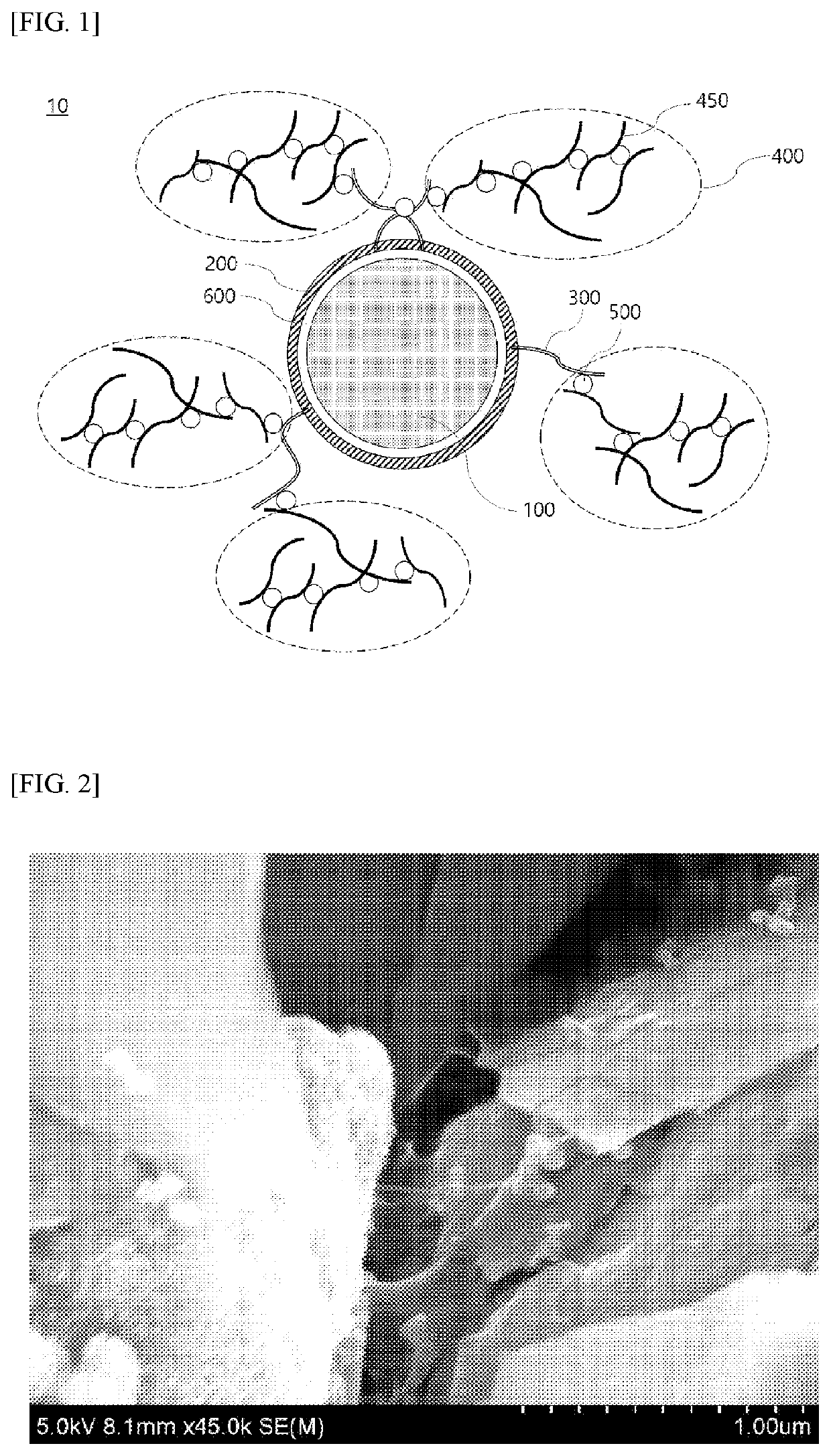
[0154]As silicon-based core particles, Mg0.1SiO particles (average particle diameter (D50): 6 μm) doped with Mg were provided.

[0155]Methane, which is a hydrocarbon gas, was deposited on the silicon-based core particles by CVD at 950° C., forming an inner carbon coating layer on the silicon-based core particle. The formed inner carbon coating layer had a weight of 5 wt % based on the total weight of the silicon-based core particle and the inner carbon coating layer.

[0156]The silicon-based core particles on which the inner carbon coating layer was formed, CMC as a precursor material for forming an outer carbon coating layer, SWCNTs, and spherical carbon black (average particle diameter (D50): 0.1 μm) as a crosslinking material were mixed in a weight ratio of 98.85:0.09:0.06:1.00.

[0157]The SWCNTs had an average length of 5 μm and an average diameter of 5 nm, and the ratio of the average length to the average diameter was 1,000.

[0158]The...

example 2

re of Composite Negative Electrode Active Material

[0162]A composite negative electrode active material of Example 2 was manufactured in the same manner as in Example 1 except that the silicon-based core particles on which an inner carbon coating layer was formed, CMC as a precursor material for forming an outer carbon coating layer, SWCNTs, and spherical carbon black (average particle diameter (D50): 0.1 μm) as a crosslinking material were mixed in a weight ratio of 98.25:0.45:0.30:1.00.

[0163]The composite negative electrode active material included the silicon-based core particle on which the inner carbon coating layer was formed, an outer carbon coating layer, the SWCNTs (first SWCNTs and second SWCNTs), and the crosslinking material in a weight ratio of 98.34:0.36:0.30:1.

example 3

re of Composite Negative Electrode Active Material

[0164]A composite negative electrode active material of Example 3 was manufactured in the same manner as in Example 1 except that the silicon-based core particles on which an inner carbon coating layer was formed, CMC as a precursor material for forming an outer carbon coating layer, SWCNTs, and spherical carbon black (average particle diameter (D50): 0.1 μm) as a crosslinking material were mixed in a weight ratio of 97.85:0.09:0.06:2.00.

[0165]The composite negative electrode active material included the silicon-based core particle on which the inner carbon coating layer was formed, an outer carbon coating layer, the SWCNTs (first SWCNTs and second SWCNTs), and the crosslinking material in a weight ratio of 97.87:0.07:0.06:2.


PUM


Abstract

A composite negative electrode active material, which includes: a silicon-based core particle; an outer carbon coating layer positioned on a surface of the silicon-based core particle; first single-walled carbon nanotubes in contact with the outer carbon coating layer, wherein the first single-walled carbon nanotubes protrude from the outer carbon coating layer; a conductive structure spaced apart from the outer carbon coating layer, wherein the conductive structure includes at least one second single-walled carbon nanotubes; and a crosslinking material bonded to the first single-walled carbon nanotube and at least one of the second single-walled carbon nanotubes. The at least one of the second single-walled carbon nanotubes is crosslinked with the first single-walled carbon nanotube by the crosslinking material, and wherein the conductive structure and the first single-walled carbon nanotube are connected to each other.

Description

CROSS-REFERENCE TO RELATED APPLICATION[0001]This application claims priority to and the benefit of Korean Patent Application No. 10-2019-0120840, filed on Sep. 30, 2019, the disclosure of which is incorporated herein by reference in its entirety.TECHNICAL FIELD[0002]The present invention relates to a composite negative electrode active material, a method of manufacturing the same, and a negative electrode including the same.BACKGROUND ART[0003]Recently, with the rapid spread of electronic devices using batteries, such as mobile phones, laptop computers, and electric vehicles, the demand for secondary batteries that are small, lightweight, and have relatively high capacity is rapidly increasing. In particular, lithium secondary batteries are lightweight and have high energy density and thus are in the spotlight as a driving power source for portable devices. Accordingly, there are on-going active research and development efforts to improve the performance of lithium secondary batteri...

Claims


Application Information

Patent Timeline
IPC IPC(8): C09C1/30H01M4/48H01M4/583H01M4/62
CPCC09C1/3054H01M4/48H01M4/583H01M4/625H01M2004/027H01M4/131H01M4/133H01M4/587H01M4/366H01M4/485H01M4/364H01M4/483C01P2006/40H01M10/052C01B33/113C01B33/22C01B32/05H01M2004/021
Inventor OH, IL GEUNLEE, YONG JUKIM, DONG HYUKKIM, YOUNG JAEKIM, YE LIN
Owner LG ENERGY SOLUTION LTD
Why Eureka
Try Eureka