Internal combustion engine ignition apparatus

Active Publication Date: 2018-10-25
MITSUBISHI ELECTRIC CORP
View PDF0 Cites 1 Cited by
  • Summary
  • Abstract
  • Description
  • Claims
  • Application Information

AI Technical Summary

Benefits of technology

[0024]An internal combustion engine ignition apparatus according to the present invention makes it possible to adjust electric power to be applied for AC plasma, in accordance with the combustion state of an internal combustion engine; thus, a spark-discharge interruption can be

Problems solved by technology

In some cases, when the EGR amount is increased, the proportion of air to be taken into the combustion chamber decreases and hence unevenness is caused in the distribution of an inflammable fuel-air mixture; thus, there exists a problem that the deterioration of ignitability causes a torque fluctuation and the like.
It is known that when an internal combustion engine utilizing a supercharger is in a high-supercharge mode, the pressure inside the combustion chamber of the internal combustion engine becomes extremely high even when no combustion occurs and hence it is difficult in this situation to produce a spark discharge for starting combustion.
One of the reasons why it is difficult to produce a spark discharge when the pressure inside the combustion chamber of the internal combustion engine is high is that the required voltage fo

Method used


Image

  • Internal combustion engine ignition apparatus
  • Internal combustion engine ignition apparatus
  • Internal combustion engine ignition apparatus

Examples


Example

Embodiment 1

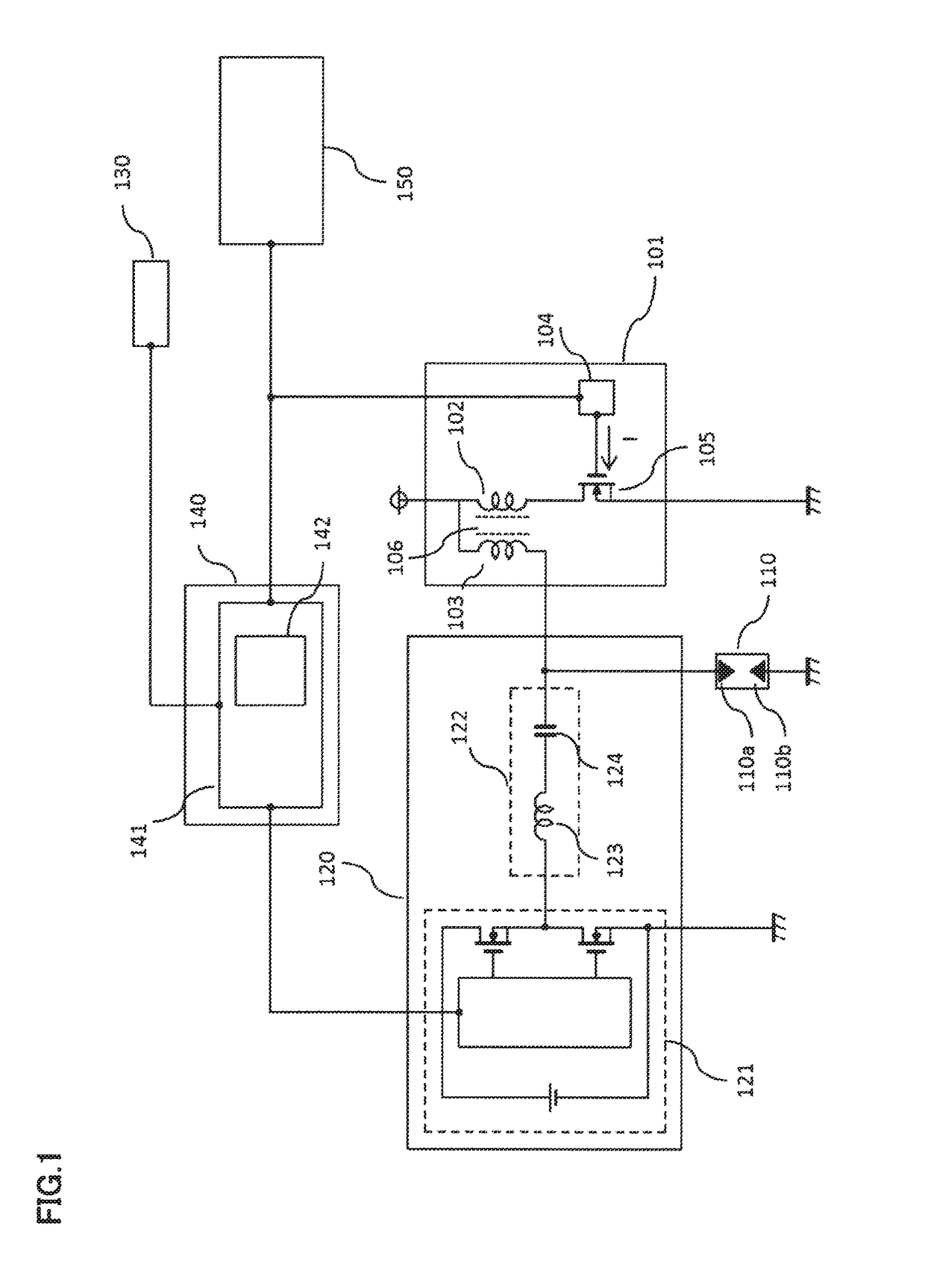
[0036]FIG. 1 is a configuration diagram of a high-frequency discharge ignition apparatus according to each of Embodiments 1, 3, and 4 of the present invention. In a high-frequency discharge ignition apparatus according to Embodiment 1 of the present invention, a spark discharge is produced between the electrodes of an ignition plug by use of a high voltage generated by an ignition coil; in addition to that, large AC plasma is formed between the central electrode and the ground electrode of the ignition plug by making a high-frequency AC current flow into the spark discharge path.

[0037]FIG. 1, the high-frequency discharge ignition apparatus according to Embodiment 1 of the present invention is mounted in a vehicle or the like and includes an energy supply apparatus 120, an ignition coil apparatus 101, a control apparatus 140, and a combustion state detection apparatus 130 for detecting a combustion state of an internal combustion engine; a spark discharge and plasma are p...

Example

Embodiment 2

[0065]Next, a high-frequency discharge ignition apparatus according to Embodiment 2 of the present invention will be explained. FIG. 4 is a configuration diagram of a high-frequency discharge ignition apparatus according to Embodiment 2 of the present invention. In contrast to the high-frequency discharge ignition apparatus according to foregoing Embodiment 1, the high-frequency discharge ignition apparatus according to Embodiment 2 of the present invention has an ion current detection apparatus 160, instead of the combustion state detection apparatus 130, in the ignition coil apparatus 101. The combustion state of the internal combustion engine is determined based on a signal obtained from the ion current detection apparatus 160. In addition, in FIG. 4, the reference numerals the same as those in FIG. 1 in Embodiment 1 denote the same or equivalent elements. The points different from Embodiment 1 will mainly be explained.

[0066]In order to detect an ion current by use of...

Example

Embodiment 3

[0080]Next, a high-frequency discharge ignition apparatus according to Embodiment 3 of the present invention will be explained. FIG. 1, described above, is a configuration diagram of a high-frequency discharge ignition apparatus according to Embodiment 3 of the present invention. In contrast to foregoing Embodiment 1, in Embodiment 3, the combustion state detection apparatus 130 detects the combustion state of the internal combustion engine, based on the inner-cylinder pressure of the internal combustion engine detected by the inner-cylinder pressure sensor. In other words, the combustion state is determined based on a signal to be obtained from the inner-cylinder pressure sensor. In. FIG. 1, the numerals that are the same as those in Embodiment 1 denote the same functions; thus, in the following explanation, the points different from Embodiment 1 will mainly be explained.

[0081]In FIG. 1, the combustion state detection apparatus 130 obtains an average effective pressure ...


PUM


Abstract

There is provided an internal combustion engine ignition apparatus that can effectively raise the ignitability of an inflammable fuel-air mixture, by applying electric power corresponding to the combustion state of an internal combustion engine. A combustion state detection apparatus detects an combustion state inside a combustion chamber of the internal combustion engine; based on the combustion state detected by the combustion state detection apparatus in accordance with an operation state of an ignition coil apparatus, a current supply apparatus supplies an AC current to a spark discharge path formed in the gap of an ignition plug; then, a control apparatus controls the output of the current supply apparatus.

Description

BACKGROUND OF THE INVENTIONField of the Invention[0001]The present invention relates to an internal combustion engine ignition apparatus that ignites an internal combustion engine by making a high-frequency AC current flow into a spark discharge path so as to form discharge plasma in a gap between the electrodes of an ignition plug.Description of the Related Art[0002]In recent years, the issues such as environment preservation and fuel depletion have been raised; measures for these issues are urgently required also in the automobile industry. As an example of the measures, there exist a method for drastically improving the amount of fuel consumption in an internal combustion engine through an internal combustion engine in which an exhaust gas recirculation (EGR) apparatus for recirculating part of exhaust gas to the intake port is mounted, engine downsizing and engine weight-saving achieved by use of a supercharger, and the like.[0003]In some cases, when the EGR amount is increased,...

Claims


Application Information

Patent Timeline
IPC IPC(8): F02P3/05F02P5/10F02P5/15F02P3/04
CPCF02P3/05F02P5/103F02P5/1516F02P3/0407F02P3/01F02P9/002F02P9/007F02P15/10F02P2017/125
Inventor KODA, TAKESHISAKAGUCHI, RYO
Owner MITSUBISHI ELECTRIC CORP
Why Eureka
Try Eureka