

Interlock assemblies for circuit breakers
- Summary
- Abstract
- Description
- Claims
- Application Information
AI Technical Summary
Benefits of technology
Problems solved by technology
Method used
Image

Examples
Embodiment Construction
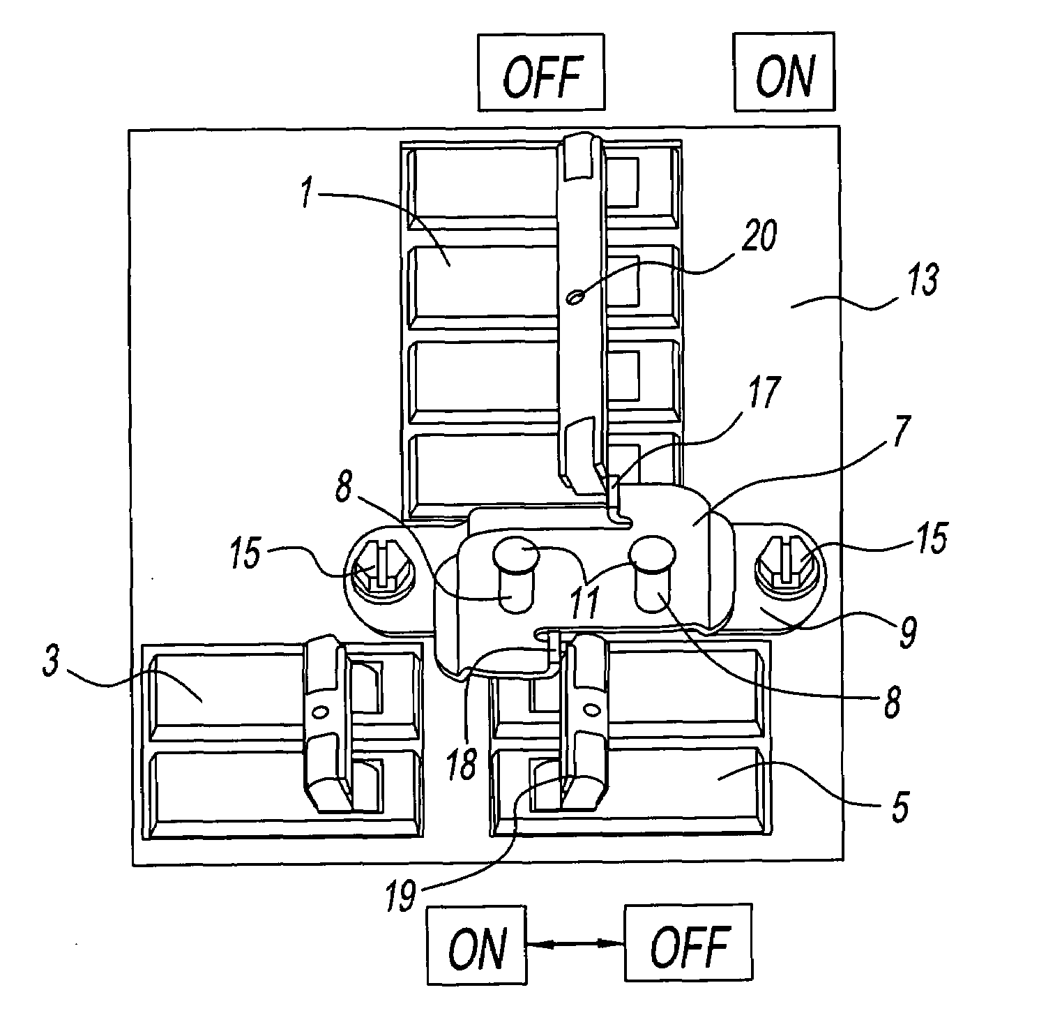
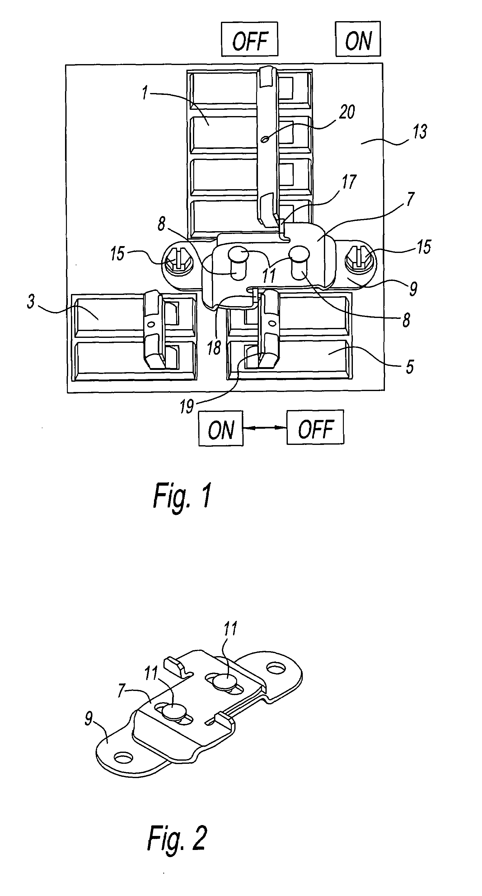
[0037]The present disclosure is best understood by reference to the attached figures, wherein FIGS. 1 and 2 provide a schematic representation of one embodiment according to the present disclosure suitable for indoor / outdoor main circuit breaker loadcenter. FIG. 1 depicts main breaker 1, branch breaker 3 and auxiliary breaker 5, wherein an interlock plate 7 with slots 8 are disposed over base plate 9 and secured thereto via rivets 11. Base plate 9 is secured to the front plate of deadfront / shield 13 of the panelboard via bolts 15. Interlock plate 7 includes oppositely disposed locking tabs 17, 18 disposed against breaker handles 19, 20, respectively. According to FIG. 1 breaker handle 19 of auxiliary main breaker 5 is locked in the “OFF” position or status, whereas breaker handle 20 of main breaker 1 is also locked in the “OFF” position.
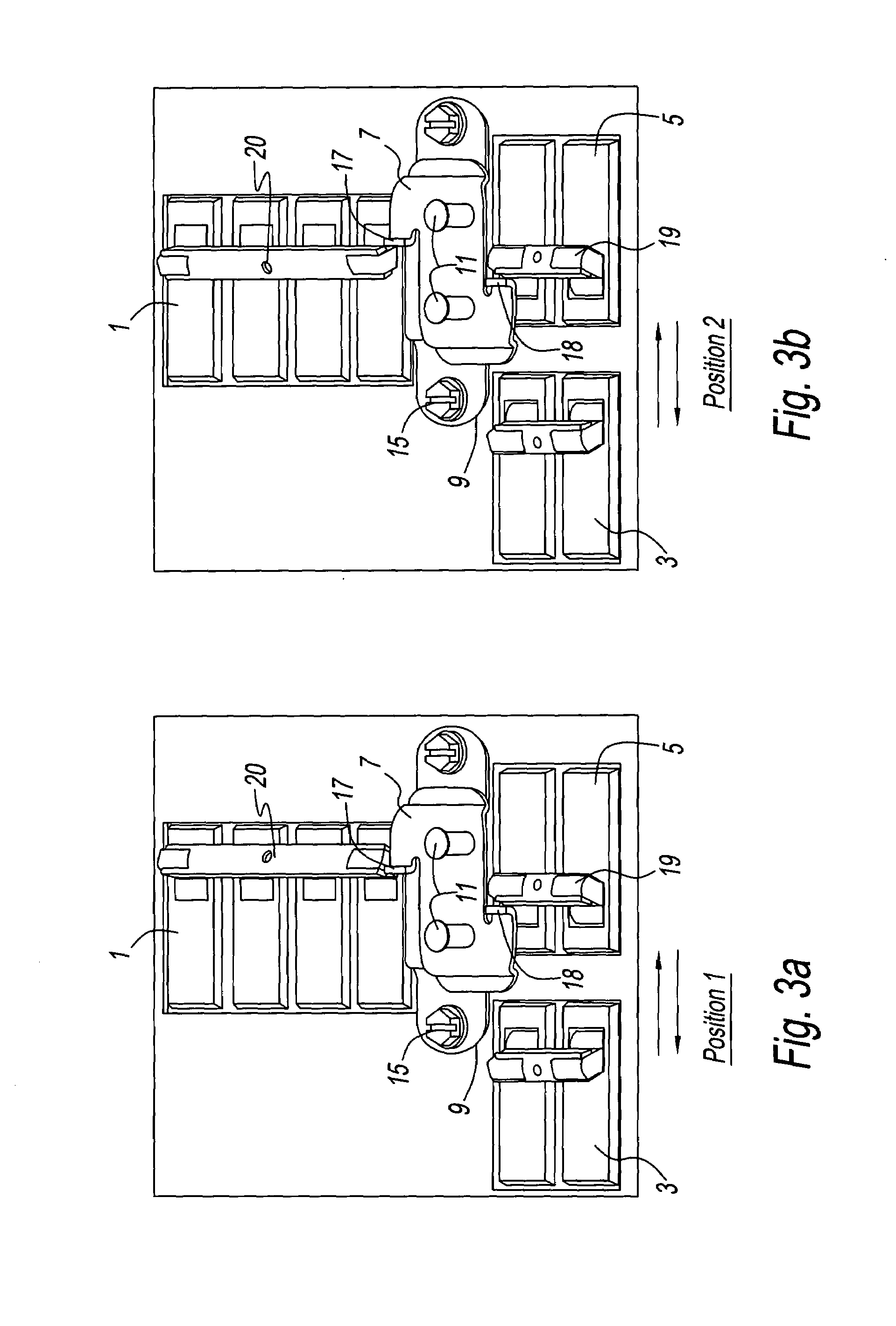
[0038]FIGS. 3a-c depicts three position of the interlocking assembly of FIG. 1, wherein FIG. 3a locks main breaker handle 20 in the “ON” position an...
PUM
 Abstract
Description
Claims
Application Information