

Mounting device for aircraft supply systems
- Summary
- Abstract
- Description
- Claims
- Application Information
AI Technical Summary
Benefits of technology
Problems solved by technology
Method used
Image

Examples
Embodiment Construction
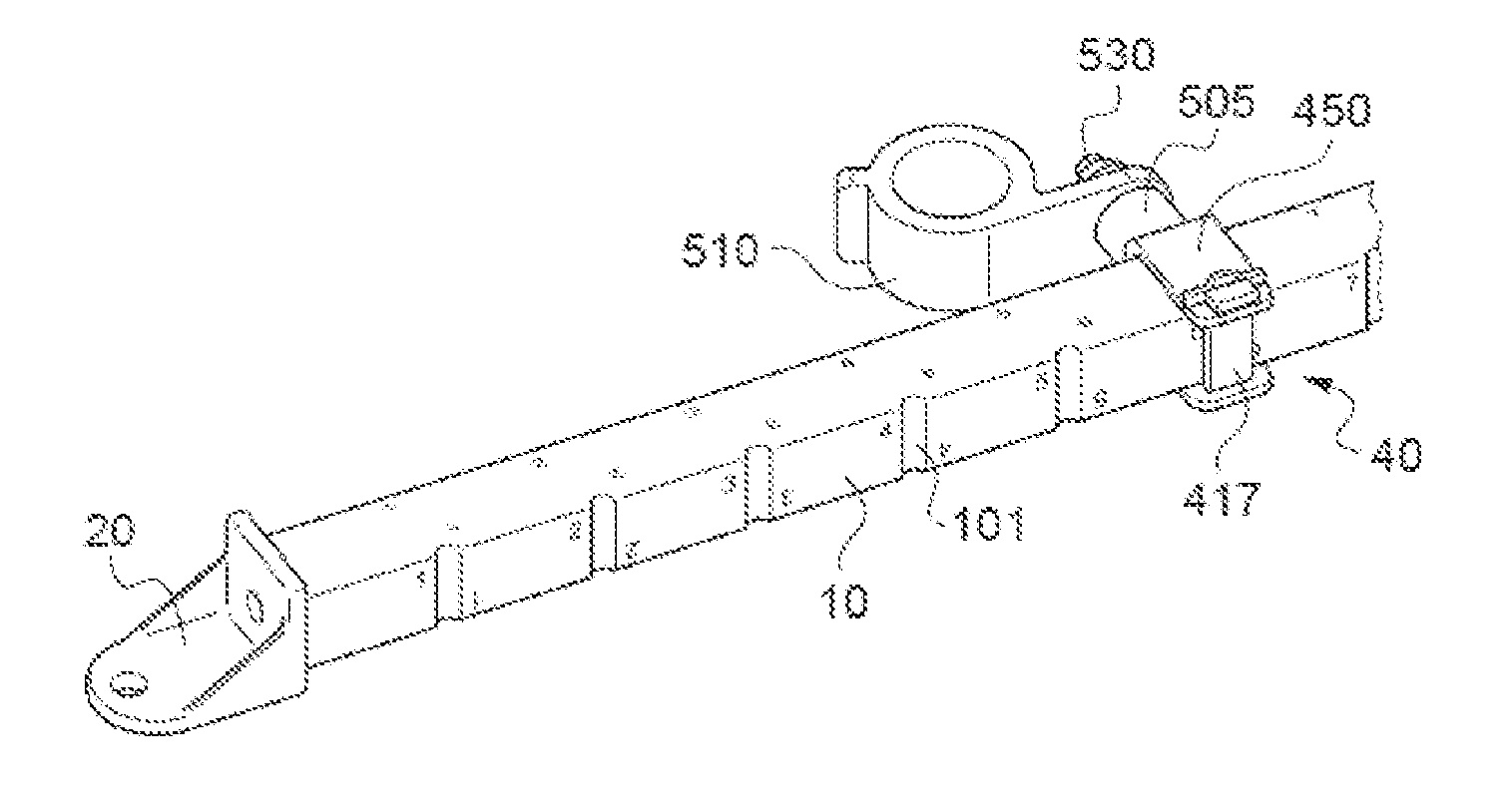
[0051]FIG. 1 shows a device 1 for mounting aircraft supply systems 2 according to a first embodiment of the invention, said device being secured to two faces 5 of the support bracket 6 of the structure of an aircraft. Since these support brackets 6 are known from the prior art and are not an integral part of the invention, their structure will not be described here.
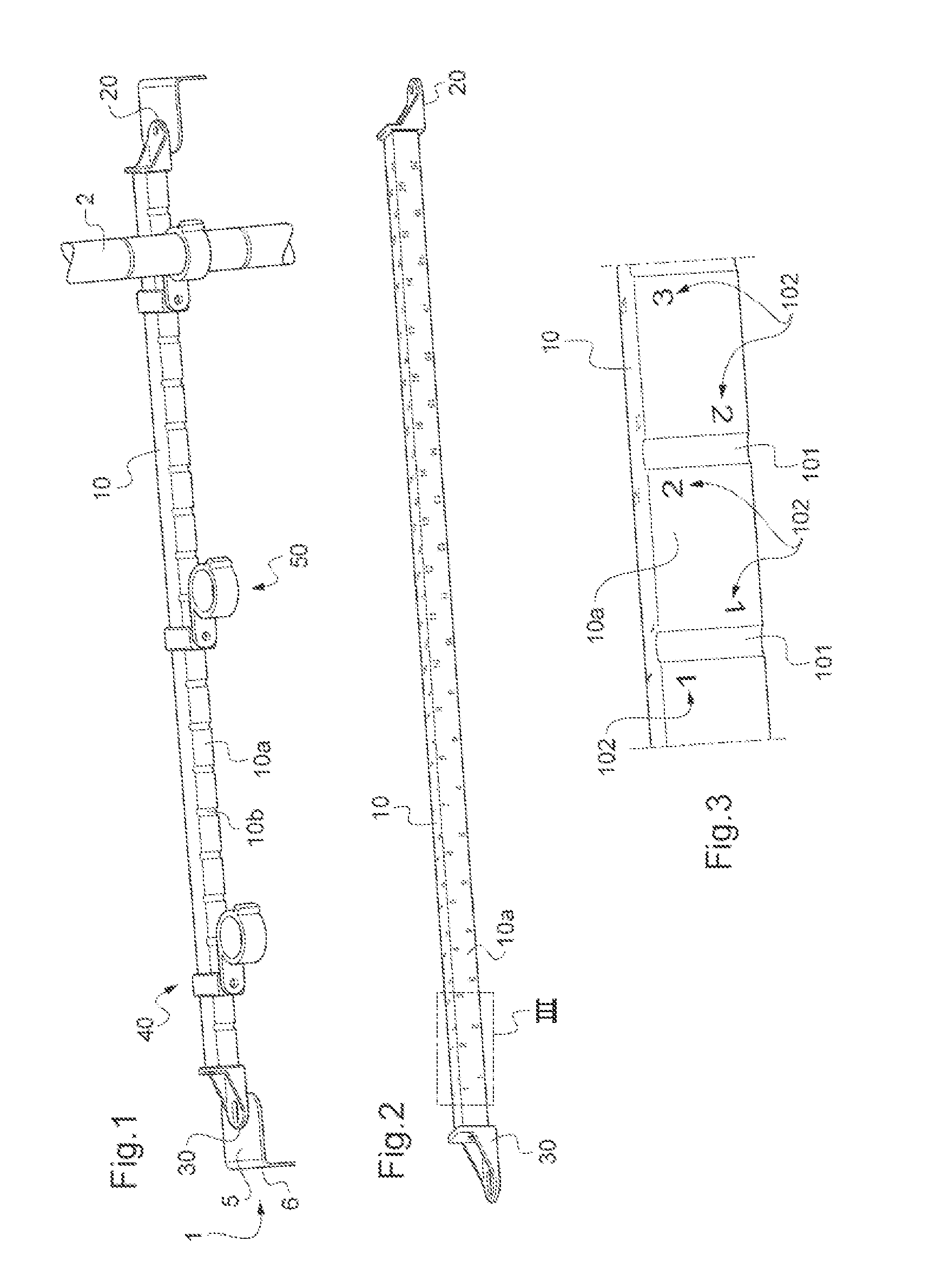
[0052]The mounting device 1 is composed of a cross member (ramp) 10, of a first end piece 20, of a second end piece 30 and of support modules 40. Intermediate devices 50 for holding supply systems, which are fixed to the modules 40, are also shown. In this case, these are collars from the prior art. As such, they will not be described in detail here.
[0053]As can be seen from FIG. 2, which shows only the cross member 10 and the first and second end pieces 20 and 30, the cross member 10 is a part which extends in a longitudinal direction and has a rectangular section. Nevertheless, it may have other sections, for example a ...
PUM
 Abstract
Description
Claims
Application Information