
Seat back of automotive seat with back board

a technology for automotive seats and back boards, which is applied in the field of seat backs of automotive seats, can solve the problems of back boards that are eventually deformed or damaged, back boards that are thin, and the rigidity of back boards will become decreased, so as to reduce the weight of back boards, prevent the creation of clearances, and reduce the effect of fuel consumption

Inactive Publication Date: 2008-06-26
TACHI S CO LTD
View PDF7 Cites 11 Cited by
  • Summary
  • Abstract
  • Description
  • Claims
  • Application Information

AI Technical Summary

Benefits of technology

[0007]In view of the above-stated drawbacks, it is a purpose of the present invention to provide a novel combination of a seat back of automotive seat and a back board securely attached to that particular seat back, which permits for reducing a weight of the back board for effective fuel economy purpose and also permits for preventing creation of clearances between the seat back and back board.

Problems solved by technology

But, when it came to attaining a light weight of seat back for fuel economy purpose, it is required to reduce the thickness of the back board, in which case, the rigidity of the back board will become decreased, with the result that, when a backward load is applied to the seat back, a padding in the seat back is thereby pressed against the back board which is eventually deformed or damaged.
Further, the reduced thickness of back board is insufficient to cause close contact of outer surfaces of the seat back with inward surfaces of the back board, so that some clearances are found between the back board and the areas of the seat back with which that particular back board is to be contacted, which results in impairing an outer aesthetic appearance of the seat back.
However, at any rate, a heavy weight of the steel angle elements adversely increases a weight of the back board, resulting in an increased weight of seat back on the whole, and costs involved in forming and securing such steel angle elements to the back board are rather expensive.

Method used


Image

  • Seat back of automotive seat with back board
  • Seat back of automotive seat with back board
  • Seat back of automotive seat with back board

Examples


Embodiment Construction

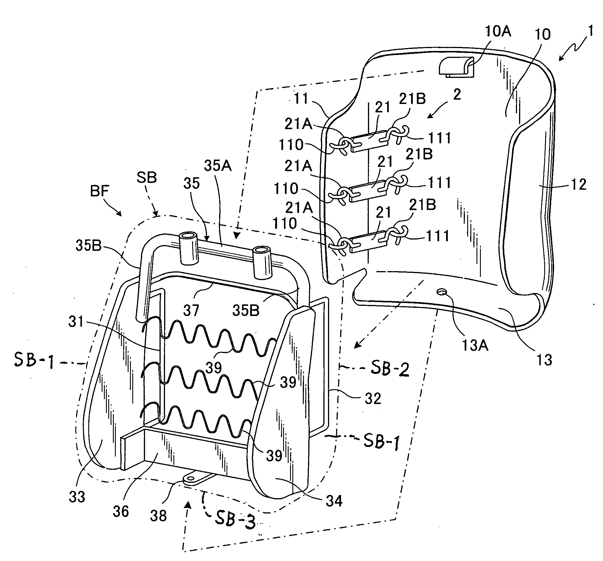
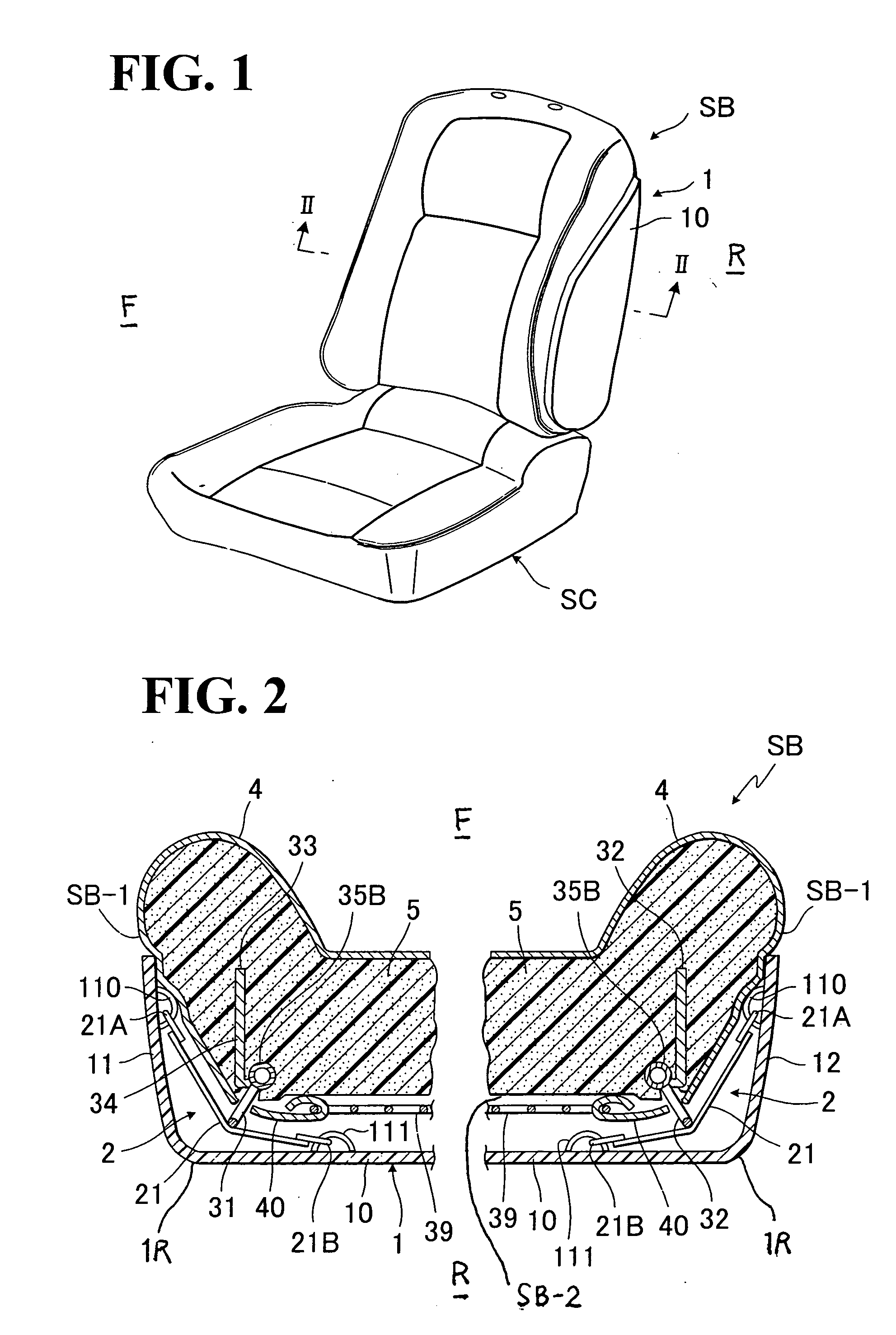
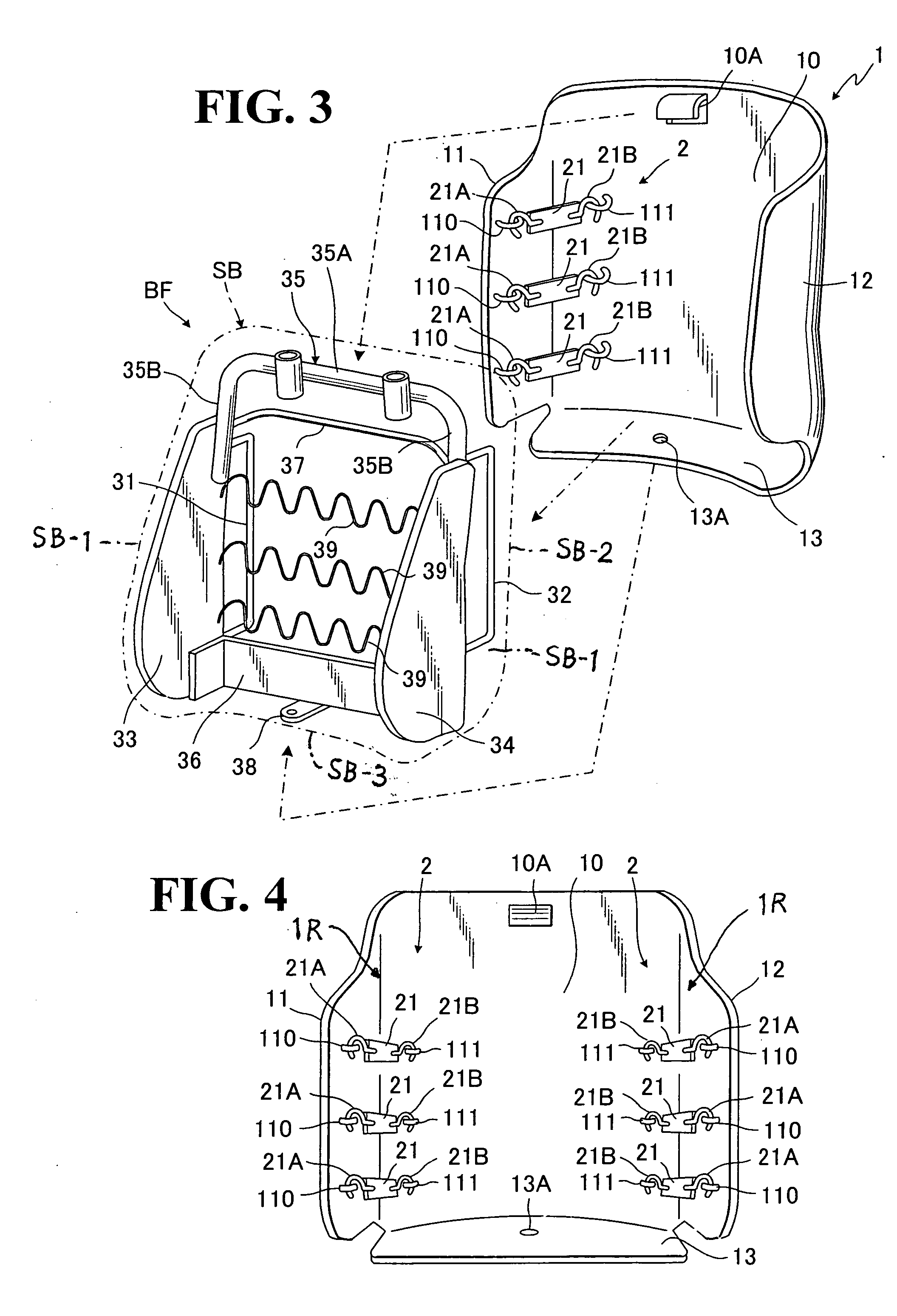
[0023]As shown in FIGS. 1 to 6, there is illustrated an exemplary preferred embodiment of a back board (1) for use with a seat back (SB) of automotive seat in accordance with the present invention.

[0024]FIG. 1 shows, in perspective, an automotive seat comprising a seat cushion (SC) and the seat back (SB).

[0025]It is noted that the term, “forward” or “forwardly”, refers to a side (F) forwardly of the seat back (SB) or the illustrative automotive seat, and the term, “rear”, “rearward” or “rearwardly”, refers to a side (R) rearwardly of the seat back (SB) or the illustrative automotive seat.

[0026]The seat back (SB) is basically constructed by a seat back frame (BF) and an upholstery composed of a trim cover assembly (4) and a foam padding (5) which are formed integrally with the seat back frame (BF), wherein the foam padding (5) is disposed on the forward side of the seat back frame (BF) as understandable from FIGS. 2 and 3.

[0027]More specifically, the known seat back frame (BF) is typ...


PUM


Abstract

A back board having a main wall region and two lateral wall regions is securely attached to a rear side of a seat back. In such combination of seat back and back bord, two presser elements, fixed to the rear side of seat back, are respectively in pressing contact with: one pressure receiving belt element extended between the main wall region of the back board and one of the two lateral wall regions of the back board; and another pressure receiving belt element extended between the main wall region of back board and another of the two lateral wall regions of back board. Thus, those two lateral wall regions of back board are resiliently bent or curved inwardly of the back board to close contact with respective two lateral sides of the seat back. The back board can be formed from a thin elastic material for light-weight purpose.

Description

BACKGROUND OF THE INVENTION[0001]1. Field of the Invention[0002]The present invention relates to a seat back of an automotive seat. In particular, the invention is directed to a combination of the seat back and a back board securely attached to that particular seat back.[0003]2. Description of Prior Art[0004]Generally stated in the filed of automotive seats, a back board for attachment to a rear side of a seat back is formed from a resin material, a hard board, a molded paper material, or the like. Normally, this sort of back board is formed to have an increased thickness by using one of those materials with a view to providing a structural rigidity and also the back board itself to be in a close contact with the contour of seat back. But, when it came to attaining a light weight of seat back for fuel economy purpose, it is required to reduce the thickness of the back board, in which case, the rigidity of the back board will become decreased, with the result that, when a backward lo...

Claims


Application Information

Patent Timeline
Patent Type & Authority Applications(United States)
IPC IPC(8): A47C7/02
CPCB60N2/58
Inventor MINAKAWA, TAKAMASAKUNIZAWA, ATSUSHI
Owner TACHI S CO LTD
Learn More