Electric machines, rotors, and rotor cages having reduced noise characteristics

a technology of electric machines and cages, applied in the field of electric machines, can solve the problems of fan blades generating an undesired noise level and undesired noise can increase beyond acceptable levels

Inactive Publication Date: 2008-06-26
GENERAL ELECTRIC CO
View PDF9 Cites 18 Cited by
  • Summary
  • Abstract
  • Description
  • Claims
  • Application Information

AI Technical Summary

Benefits of technology

[0027]FIG. 12 is a detail view of circle E in FIG. 8 illustrating the balance correction feature; and

Problems solved by technology

Unfortunately, the fan blades generate an undesired noise level.
Further, as the speed of the electric machine is increased, the undesired noise can increase beyond acceptable levels.

Method used


Image

  • Electric machines, rotors, and rotor cages having reduced noise characteristics
  • Electric machines, rotors, and rotor cages having reduced noise characteristics
  • Electric machines, rotors, and rotor cages having reduced noise characteristics

Examples


Embodiment Construction

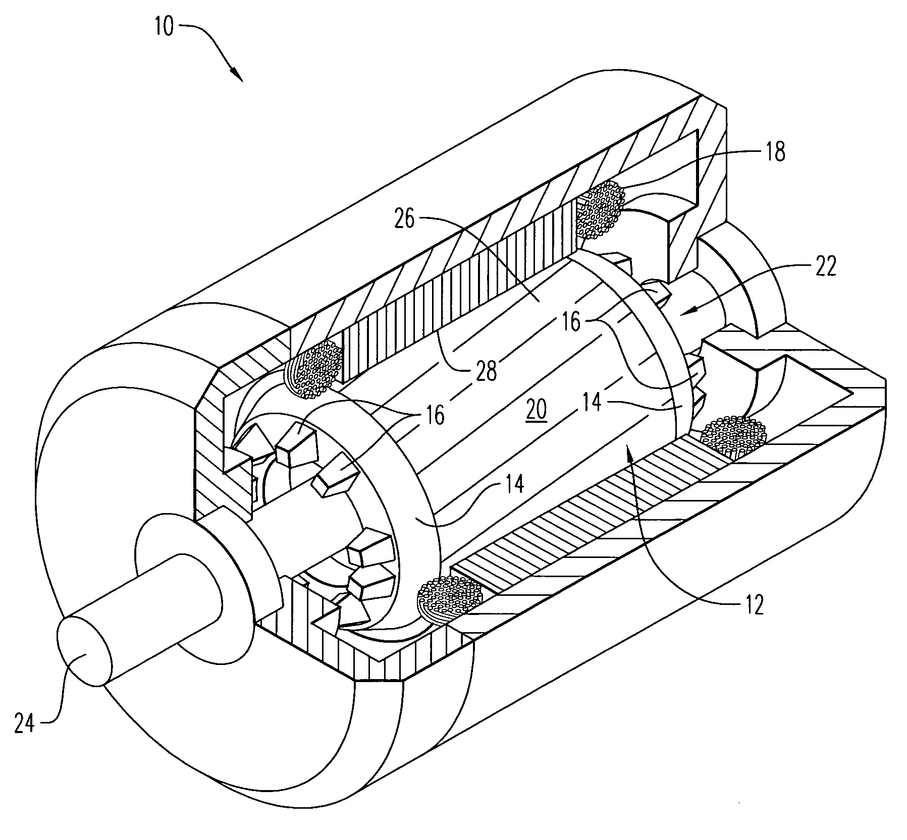
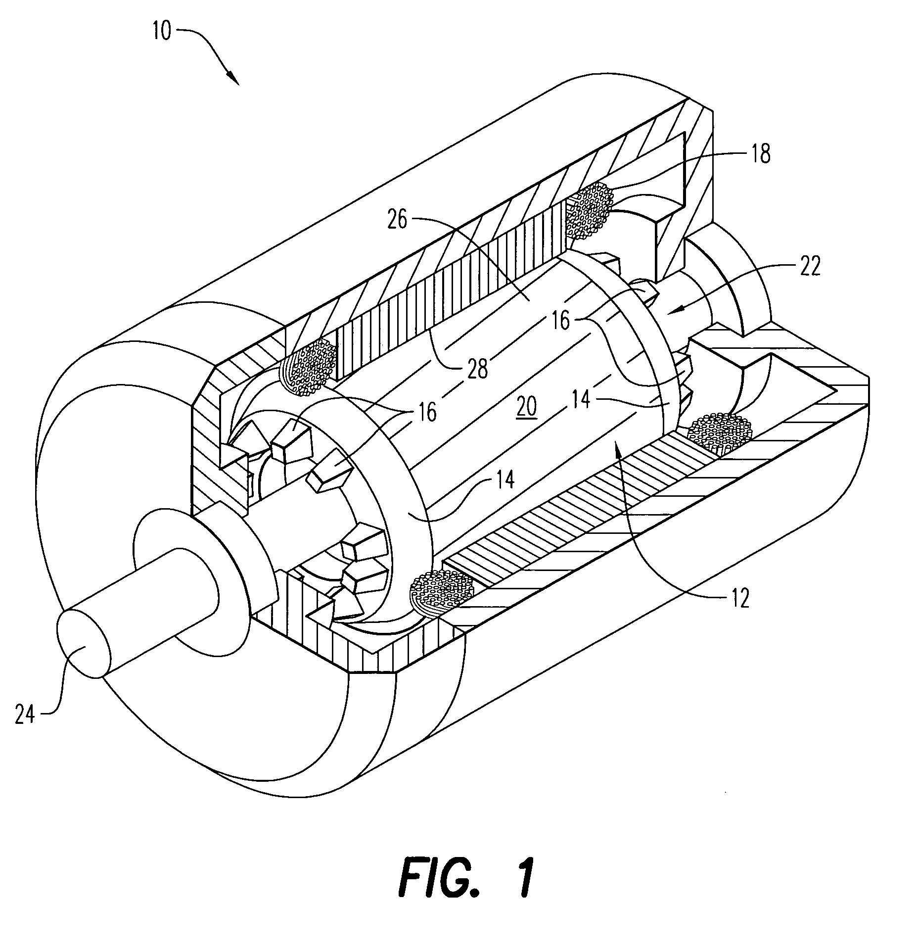
[0029]Referring to the drawings and in particular to FIG. 1, an exemplary embodiment of an electric machine according to the present disclosure is shown and is generally referred to by reference numeral 10. Machine 10 includes a rotor 12 having end rings 14 with a plurality of fan blades 16. Advantageously, end rings 14 and fan blades 16 are configured to reduce noise emitted by electric machine 10, while providing desired cooling levels to windings 18 of the motor.

[0030]Electric machine 10 is preferably an alternating current (AC) electric machine such as, but not limited to, an electric motor, an alternator, a motor-generator, and others. Rotor 12 includes a rotor core 20, a rotor cage 22, and a rotor shaft 24.

[0031]Fan blades 16 are illustrated for purposes of clarity as being blades for inducing a simple radial airflow (i.e., along the direction of shaft 24). However, fan blades 16 being configured to induce any desired airflow are contemplated for use in the present disclosure....


PUM


Abstract

A cast rotor cage for an electric machine is provided. The rotor cage includes conductor bars, a first end ring, and a second end ring. The conductor bars have a first end and a second end. The first end ring is at the first end, while the second end ring is at the second end. The first end ring has a plurality of first fan blades, where at least some the first fan blades are asymmetrically disposed on the first end ring. Similarly, the second end ring has a plurality of second fan blades, where at least some the second fan blades are asymmetrically disposed on the second end ring.

Description

BACKGROUND OF THE INVENTION[0001]1. Field of the Invention[0002]The present disclosure is related to electric machines. More particularly, the present disclosure is related to electric machines, rotors, and rotor cages having reduced noise characteristics.[0003]2. Description of Related Art[0004]Alternating current (AC) electric machines such as electric motors, alternators, motor-generators, and the like are typically constructed with a stator and a rotor rotatably mounted with respect to the stator. In one particular type of electric machine, the stator is externally positioned relative to an internally rotating rotor.[0005]In these internally rotating electric machines, the rotor typically includes a rotor core, a rotor cage, and a rotor shaft. The rotor core is constructed from a stack of generally circular laminations punched from suitable ferro-magnetic sheet material (e.g., a high magnetic permeability steel). Each of the laminations has a central opening and a plurality of n...

Claims


Application Information

Patent Timeline
Patent Type & Authority Applications(United States)
IPC IPC(8): H02K5/06H02K5/24H02K9/06H02K3/12
CPCH02K7/04H02K17/165H02K9/06
Inventor CROWELL, JAMES ROBERT
Owner GENERAL ELECTRIC CO
Why Eureka
Try Eureka