Tampon Applicator

a technology of applicators and ejector tubes, which is applied in the field of tampon applicators, can solve the problems achieve the effects of reducing the likelihood of disassembly

Inactive Publication Date: 2008-06-26
ONTEX HIGIENEARTIKEL DEUT GMBH
View PDF89 Cites 25 Cited by
  • Summary
  • Abstract
  • Description
  • Claims
  • Application Information

AI Technical Summary

Benefits of technology

[0012]The present invention provides a tampon applicator of the type employing telescopic tubes, comprising a novel restraining means for preventing the disassembly of the tubes when said tubes are pulled apart in normal use. The restraining means of the present applicator advantageously reduces lateral wobble between the applicator tubes, both while the tubes are only partially removed from each other, as well as when the restraining means is in interlocked position, i.e., when the structures of the restraining means are mutually interlocked and the applicator is cocked. Limiting of the wobble greatly reduces the likelihood of disassembly.
[0014]Hence, while the prior art has only provided for a pair of two raised rings on the inner surface of the outer tube, said pair forming a valley which could accommodate a corresponding ring-like raised means on the outer surface of the ejector tube, the present invention provides for at least one additional ring on the inner surface of the outer tube, which contacts or is in close proximity with the outer surface of the ejector tube. The additional ring provides an extra means of restricting the lateral movement and the resulting wobble of the ejector tube relative to the outer tube. Preferably, the additional ring may be provided close to the proximal end of the outer tube, that is at a location where it can maximally restrict the lateral movement of the ejector tube. Advantageously, the additional ring may be spaced away from the interlocked rings, whereby the applicator comprises at least two relatively distant points of close contact between the surfaces of the ejector tube and the outer tube. These points of contact may work synergistically to inhibit the lateral wobble of the ejector tube.
[0015]The provision of the additional ring restricting the lateral movement of the ejector tube removes the requirement for an exact match between the respective facing surfaces of the interlocked structures, i.e., the raised means and the valley, as the wobble is prevented already if only one surface of the raised means closely engages with one corresponding surface of the valley. This improvement greatly simplifies the production process, as it is not anymore absolutely critical that the corresponding interlocking structures have perfectly complementary dimensions and shapes.
[0016]Advantageously, the valley may be broader than the raised means and may provide for some freedom of axial movement of the ejector tube in interlocked position. Therefore, the user will be able to sense when the boundaries of such freedom of axial movement are being approached and may adequately increase the force in order to smoothly overcome these boundaries. In particular, this may allow the user to smoothly push the ejector tube from interlocked position back into the outer tube during disposal of the tampon.
[0017]The present invention also removes the need for increasing the width of the distal one of the two rings on the outer tube, which may result in savings of raw material and decreased cost of production.
[0018]Furthermore the present invention also provides for restricting the wobble not only in interlocked position, but also when the ejector tube is less removed from the outer tube, which simplifies the manipulation of the applicator.

Problems solved by technology

Limiting of the wobble greatly reduces the likelihood of disassembly.

Method used


Image

  • Tampon Applicator
  • Tampon Applicator

Examples


Embodiment Construction

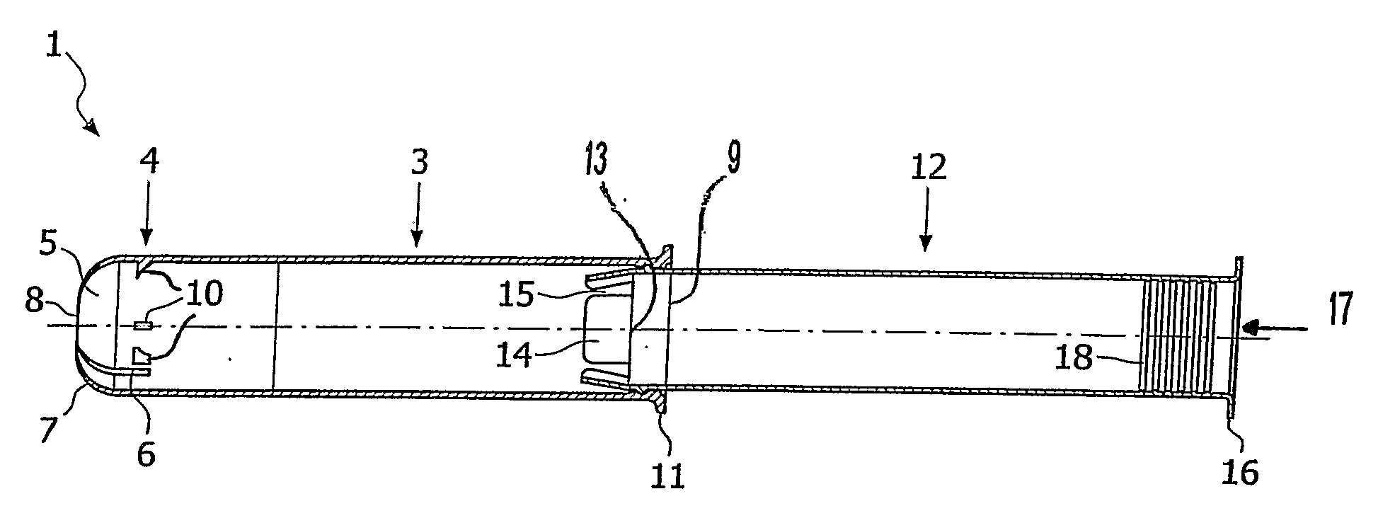
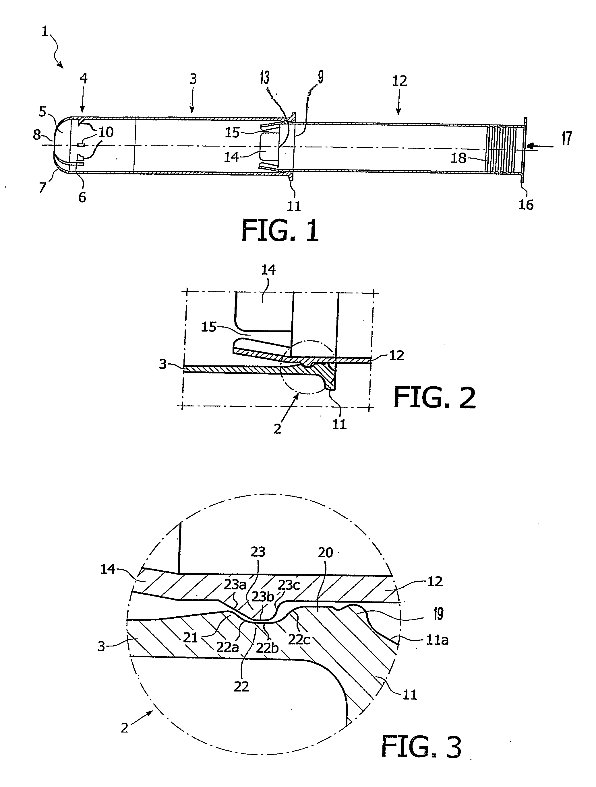
[0022]The present invention provides a tampon applicator of the type employing telescopic tubes, comprising a novel restraining means. The novel restraining means may be used with essentially any tampon applicator of the abovementioned type. FIG. 1 illustrates a preferred, but non-limiting example of such applicator 1 which comprises an ejector tube 12 adapted to store a tampon therein and an outer tube 3 slideably disposed over the ejector tube 12. The outer tube 3 is adapted to pass the tampon through its distal end 4 during an ejection operation.

[0023]The cylindrical outer tube 3 has at its distal end 4 conventional petal sections 5 which are separated from each other by respective slots 6. The petal sections 5 are made relatively flexible and are normally biased in a substantially arcuate closed configuration to form a rounded tip 7 having a central opening 8 at the distal end 4. This rounded shape of the distal end 4 helps facilitate the insertion of the applicator 1 into the v...


PUM


Abstract

A tampon applicator which includes an ejector tube, an outer tube dimensioned to fit closely and telescopically over said ejector tube and having a distal discharge end, and a restraining means between said tubes for preventing the disassembly of said ejector tube from said outer tube in the proximal direction is disclosed. The restraining means includes a circumferentially-extending raised means and a set of at least three adjacent circumferentially-extending raised rings.

Description

FIELD OF THE INVENTION[0001]The present invention relates to tampon applicators and, more particularly, is directed to compact catamenial tampon applicators of the type employing telescoping tubes comprising restraining means for interlocking said tubes.BACKGROUND OF THE INVENTION[0002]Most commercially available tampon applicators for introducing catamenial tampons intravaginally consist of a pair of telescoping tubes.[0003]In a compact tampon applicator design the ejector tube is telescoped completely into the outer tube while the tampon is stored in the distal end of the ejector tube. Operatively, the ejector tube is “cocked” by being withdrawn proximally out most of the way from its stored position in the outer tube (leaving behind the tampon) until the distal end of the ejector tube is positioned to engage the proximal end of the stored tampon. Different ways of securing the stored tampon in the distal end of the outer tube to prevent proximal displacement of the tampon while t...

Claims


Application Information

Patent Timeline
Patent Type & Authority Applications(United States)
IPC IPC(8): A61F13/20
CPCA61F13/26
Inventor VAN INGELGEM, WERNERDE POORTER, ANNICKSMET, STEVEN
Owner ONTEX HIGIENEARTIKEL DEUT GMBH
Why Eureka
Try Eureka