Supercharge Your Innovation With Domain-Expert AI Agents!

Manufacturing method for winding assembly of rotating electrical machine and manufacturing apparatus for the winding assembly

a manufacturing method and technology of rotating electrical machines, applied in the direction of instruments, apparatus for web record carriers, magnetic bodies, etc., can solve the problems of difficult to change the work time of the weaving step becomes long, and the length of the first and the second straight parts is still limited, so as to reduce the number of times of weaving.

Active Publication Date: 2008-07-03
MITSUBISHI ELECTRIC CORP
View PDF13 Cites 2 Cited by
  • Summary
  • Abstract
  • Description
  • Claims
  • Application Information

AI Technical Summary

Benefits of technology

The method significantly reduces the number of weaving operations, eliminates the push-out step, and integrates lead wire formation, thereby enhancing work efficiency and productivity in manufacturing winding assemblies for rotating electrical machines.

Problems solved by technology

However, in the plate-like winding cores disclosed in this prior art, since the width between the plural projections provided at one side of the outer periphery and the plural projections provided at the other side is fixed, and the lengths of the first and the second straight parts are fixed by the width, it is difficult to change the lengths of the first and the second straight parts.
In order to change the lengths of the first and the second straight parts, although plate-like winding cores with different widths are prepared, the change of the lengths of the first and the second straight parts is nevertheless limited.
Further, since the number of winding members wound at one winding step is small, in order to mutually weave more winding members at the weaving step, the number of times of weaving is required to be made large, the work time of the weaving step becomes long, and the work efficiency is low.
However, the extrusion by the push-out member is required to be performed by specially providing the push-out step after the turn step of the wire rod on the turn plane is ended, and the whole work time of the winding step becomes long by this push-out step, and the work efficiency becomes low.

Method used


Image

  • Manufacturing method for winding assembly of rotating electrical machine and manufacturing apparatus for the winding assembly
  • Manufacturing method for winding assembly of rotating electrical machine and manufacturing apparatus for the winding assembly
  • Manufacturing method for winding assembly of rotating electrical machine and manufacturing apparatus for the winding assembly

Examples


embodiment 1

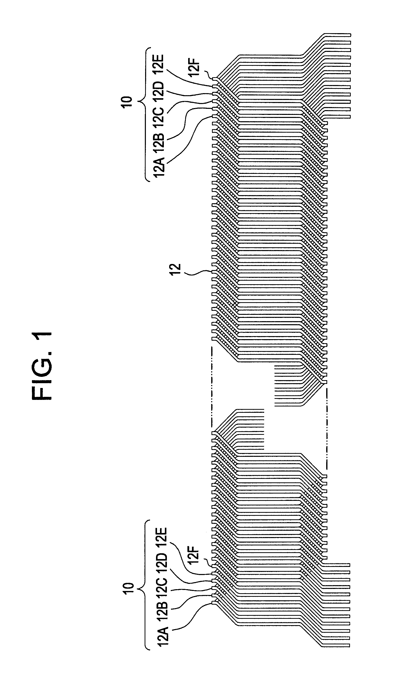
[0066]Embodiment 1 relating to the manufacturing method for the winding assembly 10 of the rotating electrical machine according to this invention will be described.

[0067]The manufacturing method for the winding assembly 10 according to this invention is carried out in the order of a winding step, a displacement step, a press step and an insertion step. First, the winding step of the winding assembly 10 according to this invention will be described, and then, the displacement step, the press step, and the insertion step will be described.

20 Used>

[0068]The main structure of the manufacturing apparatus 20 used in the winding step of embodiment 1 is shown in FIG. 4. FIG. 4(a) is a plan view thereof, and FIG. 4(b) is a side view thereof. As shown in FIGS. 4(a) and 4(b), this manufacturing apparatus 20 includes a turn mechanism 30 and a wire rod feed mechanism 60, and simultaneously and helically winds all twelve winding members 15 constituting the winding assembly 10. Since the winding ...

embodiment 2

[0112]Next, embodiment 2 of a manufacture method for a winding assembly of a rotating electrical machine according to this invention will be described with reference to FIGS. 16 to 20.

[0113]According to this embodiment 2, a winding step includes a lead wire formation step SLW of forming a lead wire 17a at a set position for a winding member selected from plural winding members wound. This lead wire formation step SLW is carried out by a lead wire preparation step SLP carried out subsequently to an nth first or second wire rod feed step S1 or S3 (n is an arbitrary natural number) and by an nth first or second wire rod turn step S2 or S4 subsequent to this lead wire preparation step SLP. The first or second wire rod turn step S2 or S4 subsequent to this lead wire preparation step SLP is called a lead wire additional formation turn step STL. At the lead wire additional formation turn step STL, the lead wire 17a is formed in addition to a first straight part 15A and a first turn part 15...

embodiment 3

[0132]Similarly to embodiment 2, embodiment 3 relates to a manufacturing method for a winding assembly of a rotating electrical machine in which a lead wire is formed in a winding step of a winding assembly 10, and is an embodiment in which embodiment 2 is modified and one more lead wire 17b is formed subsequently to one lead wire 17a.

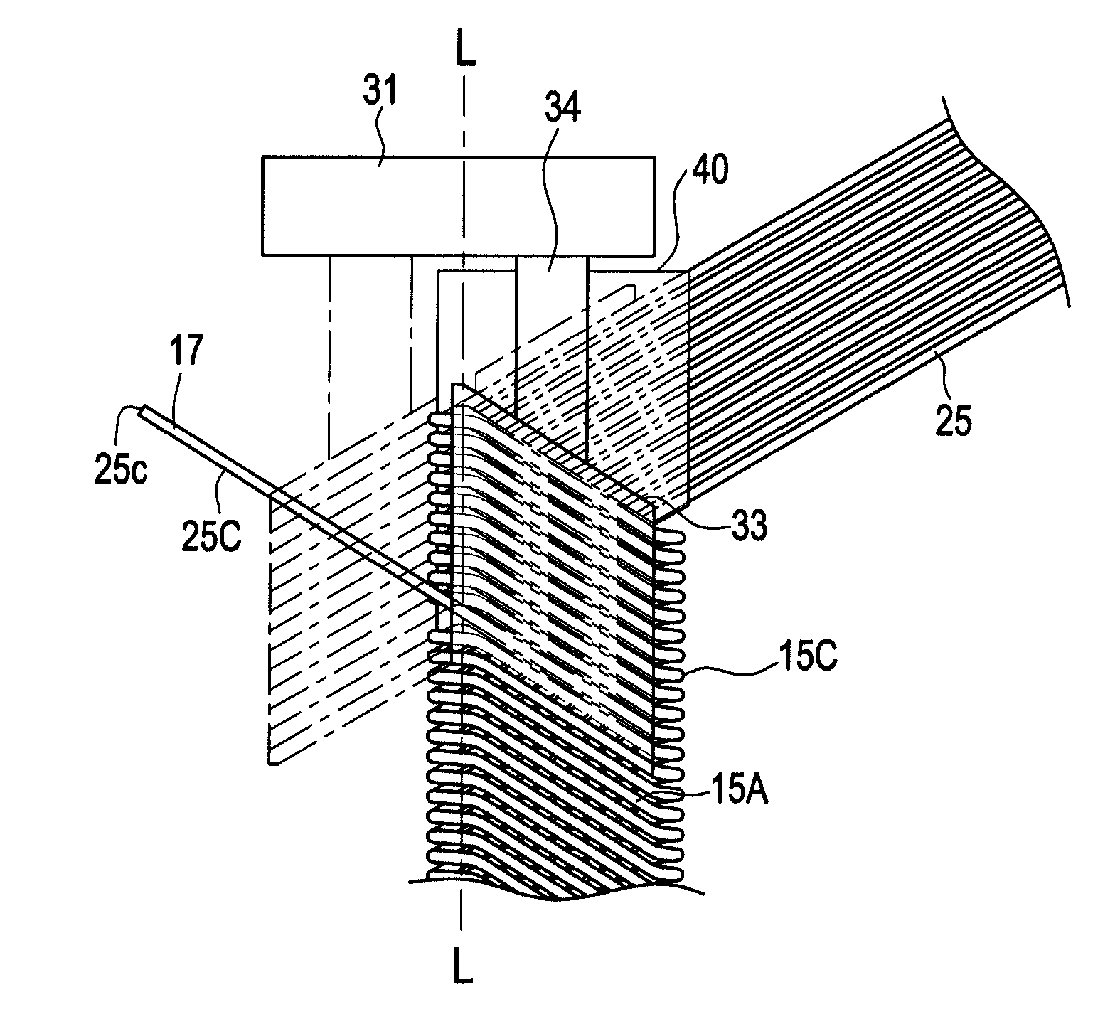
[0133]FIGS. 21(a) and 21(b) show a state in which after one lead wire 17a is formed similarly to embodiment 2, one more lead wire 17b is formed. FIGS. 21(a) and 21(b) show the state in which after the lead wire 17a is formed, the lead wire 17b is formed in the state where the rotation block 33 exists on the second reference surface F-F. Although the state shown in FIGS. 21(a) and 21(b) corresponds to the state shown in FIGS. 18(a) and 18(b) of embodiment 2, the lead wire 17b is additionally formed.

[0134]In the state shown in FIGS. 16(a) and 16(b), the wire rod 25-11 cut at the cut place 25c by the cutting mechanism 70 includes the wire rod portion 25D...


PUM


Abstract

There are proposed a manufacturing method of a winding assembly of a rotating electrical machine using a rotation block and a fixed block and a manufacturing apparatus used for the same. The rotation block includes a rotation surface rotatable around a rotation axis, and the fixed block includes a first surface and a second surface opposite to each other and a shaping surface. The shaping surface is formed between end parts of the first and the second surfaces, is made to have an almost semicircular shape with the rotation axis as the center, and extends along the rotation axis. Plural wire rods are simultaneously fed from the first surface of the fixed block to the rotation surface of the rotation block, and the wire rods positioned on the rotation surface are bent by rotation of the rotation block.

Description

[0001]This is a divisional of application Ser. No. 10 / 550,560 filed Sep. 26, 2005. The entire disclosure of the prior application, application Ser. No. 10 / 550,560 is hereby incorporated by reference.TECHNICAL FIELD[0002]The present invention relates to a manufacturing method for a winding assembly of a rotating electrical machine used for a vehicle AC generator mounted in a vehicle such as, for example, a passenger car or a truck, and a manufacturing apparatus for the winding assembly.BACKGROUND ART[0003]The applicant of this application proposed a technique to improve the mass productivity of a winding member and a winding assembly used for this type of rotating electrical machine in JP-A-2002-176752. In this prior art, a winding assembly of a rotating electrical machine includes plural winding combinations, and each of the winding combinations are constructed by combining two winding members. Each of the winding members is wound by continuously turning a wire rod so as to have a f...

Claims


Application Information

Patent Timeline
Patent Type & Authority Applications(United States)
IPC IPC(8): H02K15/04
CPCH02K15/0435Y10T29/5137Y10T29/49096Y10T29/49073Y10T29/49009Y10T29/49071Y10T29/49066Y10T29/49062Y10T29/49012Y10T29/4902Y10T29/53143Y10T29/4906H02K15/0478
Inventor HIROTA, YUTAKAMURATA, NORIHIROKASHIHARA, TOSHIAKI
Owner MITSUBISHI ELECTRIC CORP
Features
  • R&D
  • Intellectual Property
  • Life Sciences
  • Materials
  • Tech Scout
  • Unparalleled Data Quality
  • Higher Quality Content
  • 60% Fewer Hallucinations
Learn More