Shoe Having Cushioning System

a cushioning system and shoe technology, applied in the field of shoes, can solve the problems of limited lifetime, low cushioning performance, comparatively high weight, etc., and achieve the effects of low overall weight of the shoe, improved cushioning properties, and convenient manufacture of the sho

Active Publication Date: 2008-07-03
ADIDAS
View PDF18 Cites 11 Cited by
  • Summary
  • Abstract
  • Description
  • Claims
  • Application Information

AI Technical Summary

Benefits of technology

[0012]The arrangement of the angled lever and the deformation element according to embodiments of the present invention serves to transform a vertical cushioning movement in the shoe sole into a deformation movement of the deformation element. This is because the vertical cushioning movement of the upper sole element in the direction of the lower sole element causes a rotation of the lever and thereby a deformation of the deformation element attached to the first arm of the lever. This leads to maximum use of the available space between the sole elements. In contrast to the simple compression of cushioning materials such as EVA or the above mentioned designs of the prior art, the arrangement of the angled lever allows the exclusion of almost any residual volume between the two sole elements. Accordingly, a long cushioning movement is made possible without the sole becoming excessively thick. The above explained “bottoming out” can therefore be reliably avoided and the muscles and joints of an athlete are protected without increasing the risk of spraining the ankle and the weight of the shoe. At the same time, the life-time of the shoe is significantly increased. Due to the angled shape of the lever, the vertical compression movement is transformed into a deformation movement by a single component. The manufacturing effort of the arrangement of embodiments of the present invention is therefore substantially lower than in the prior art mentioned above.
[0014]A particularly advantageous cushioning characteristic can be achieved, if the angled lever is shaped such that a vertical cushioning movement by a distance x of the upper sole element in a downward direction approaching the lower sole element leads to an elongation of the elongation element by a distance y, wherein the distance y is less than the distance x. In other words, a vertical cushioning movement, when the shoe is loaded, e.g. during the first ground contact with the heel, is effectively reduced to a smaller elongation movement of the elongation element. Such a reducing transformation of the vertical cushioning movements allows comparatively long vertical cushioning paths without an excessive elongation movement. As a result, large and therefore comfortable cushioning movements can be realized with a comparatively compact arrangement of the described cushioning system of the shoe.
[0016]In an embodiment, the cushioning system comprises at least two angled levers, which are arranged on opposite sides of the shoe, for example, on the lateral and the medial side of the heel part. In one embodiment, there are lateral and medial deformation elements which can be deformed essentially independently from each other. Mis-orientations such as pronation or supination can simply be corrected by using different deformation elements for the medial and the lateral side. Such a modular design also allows a manufacturer, a retailer or even the user to adapt the shoe to the individual needs of the user and / or a specific type of sport. Further, such a modular design generally facilitates the manufacture of the shoe using a suitable toolbox and the required parts.
[0017]In one embodiment, the lower sole element is provided as a sole surface and the upper sole element as a sole cup adapted to the anatomy of the foot. As a result, the pressure is distributed over essentially the complete area so that point loads on the foot sole are excluded. Apart from an additional outsole layer, which is preferably arranged directly on the lower side of the lower sole surface, the sole comprises preferably no further components in this region. Thus, the improved cushioning properties can be achieved at a comparatively low overall weight of the shoe. In some embodiments, a conventional outsole element can be attached under the lower sole element. Similarly, the upper sole element can be attached to a conventional midsole or insole, or the like.

Problems solved by technology

Shoe soles are subjected to substantial compressive loads.
Although this material provides good cushioning properties, it has a limited lifetime.
Further disadvantages are the temperature dependency of the cushioning properties of EVA and the comparatively high weight.
However, the structural deformation elements tend to be slightly stiff and in a similar manner to foamed EVA cushioning elements only provide a limited cushioning movement.
Practically, however, only a fraction of the distance to the ground can actually be used for the cushioning movement, since the compressed cushioning material takes up a significant residual volume below the sole of the foot.
If the initial volume is increased, the shoe becomes unstable and a spraining to the side may cause severe injuries.
Furthermore, the increased amount of cushioning material leads to a greater weight of the shoe, which is undesirable for most sports shoes.
This design is very complex and leads to a substantial residual volume which restricts the available cushioning movement.
Furthermore, the design is so complex that it is inconceivable to economically manufacture the corresponding shoe.
The design of the toggle levers is complex and requires the assembly of a plurality of straight rods having lugs at their ends for receiving a plurality of axles.
In this position it can easily be damaged and causes an accumulation of dirt which impairs the cushioning movement.

Method used


Image

  • Shoe Having Cushioning System
  • Shoe Having Cushioning System
  • Shoe Having Cushioning System

Examples


Embodiment Construction

[0029]In the following, embodiments of the invention are further described with reference to a sports shoe. However, it is to be understood that the present invention can be used in a plurality of different types of shoes. The invention is particularly relevant for shoes which are subjected to high loads, for example continuous loads such as in a running shoe or peak loads such as in a basketball shoe.

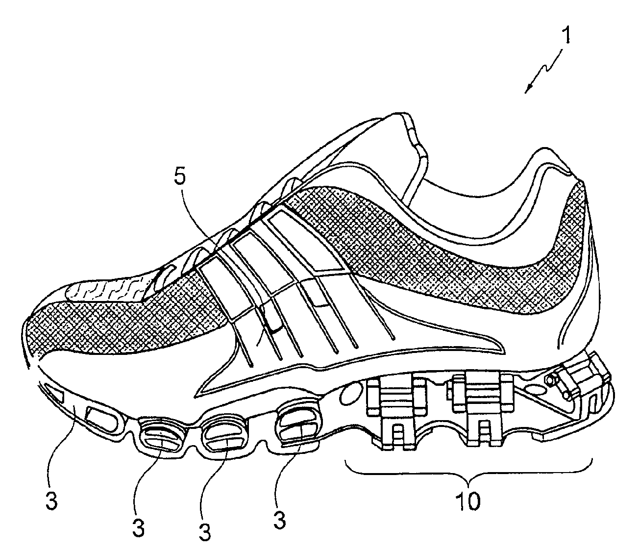
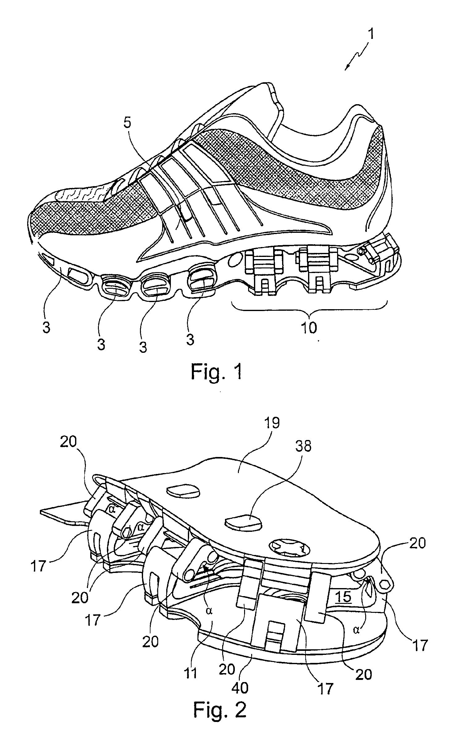
[0030]FIG. 1 presents a side view of a shoe 1 having in the rear part of the sole a cushioning system 10 which is further explained below. It is also possible to arrange the cushioning system 10 in the forefoot part or in other parts of the sole. However, the highest ground reaction forces occur in the heel part which makes an optimal cushioning system particularly important.

[0031]Standard cushioning elements are preferably arranged in the forefoot part of the shoe 1, as shown in FIG. 1, for example foamed elements (not shown) or the structural deformation elements 3 without foamed mat...


PUM

PropertyMeasurementUnit
angleaaaaaaaaaa
angleaaaaaaaaaa
angleaaaaaaaaaa

Abstract

The present invention relates to a shoe, in particular a sports shoe, with a cushioning system comprising a lower sole element and an upper sole element. The cushioning system further comprises at least one lever having at least two arms where an angle α between the arms lies within the range 0°<α<180°. The first arm is connected to a deformation element and the second arm is connected to one of the two sole elements, wherein the lever is pivotably arranged at the other sole element.

Description

BACKGROUND OF THE INVENTION[0001]1. Field of the Invention[0002]The present invention relates to a shoe, in particular a sports shoe with a cushioning system.[0003]2. Background Art[0004]Shoe soles are subjected to substantial compressive loads. Particularly in sports shoes, there are ground reaction forces resulting when the shoe contacts the ground with the heel and during push-off at the end of the step cycle exceed the body weight. Accordingly, a sole construction must on the one hand provide a sufficient cushioning comfort to avoid premature fatigue or even injuries of the muscles or the bones. On the other hand, it must be capable to withstand these forces over an acceptable lifetime.[0005]In sports shoes, for example running shoes, cushioning elements made out of foamed materials such as ethylene-vinyl-acetate (EVA) are typically arranged in the sole. Although this material provides good cushioning properties, it has a limited lifetime. For example runners with a high monthly...

Claims


Application Information

Patent Timeline
Patent Type & Authority Applications(United States)
IPC IPC(8): A43B13/00A43B13/18A43B21/32A43B21/24
CPCA43B3/0042A43B3/0068A43B21/30A43B21/26A43B13/181
Inventor LUCAS, TIMOTHY DAVIDMANZ, GERD RAINERCHANDLER, MATTHEW DANIELSMITH, PAUL LEONARD MICHAELGORDON, JOSH ROBERTRIPPEL, MANFREDLEIMER, ROBERTHILL, JAN
Owner ADIDAS
Why Eureka
Try Eureka