Finned Strainer

a strainer and filter technology, applied in the field of filters, can solve problems such as loss of coolan

Active Publication Date: 2008-07-03
ATOMIC ENERGY OF CANADA LIMITED
View PDF20 Cites 26 Cited by
  • Summary
  • Abstract
  • Description
  • Claims
  • Application Information

AI Technical Summary

Benefits of technology

[0006]In accordance with one aspect of the invention there is provided a strainer for filtering debris from a fluid comprising an elongated header defining an enclosed flowpath, having an outlet in fluid communication with a suction source and a plurality of inlet apertures disposed along the length of said flowpath, said flowpa

Problems solved by technology

One such scenario is a “loss of coolant accident,” in which an external pipe is postulat

Method used


Image

  • Finned Strainer
  • Finned Strainer
  • Finned Strainer

Examples


Embodiment Construction

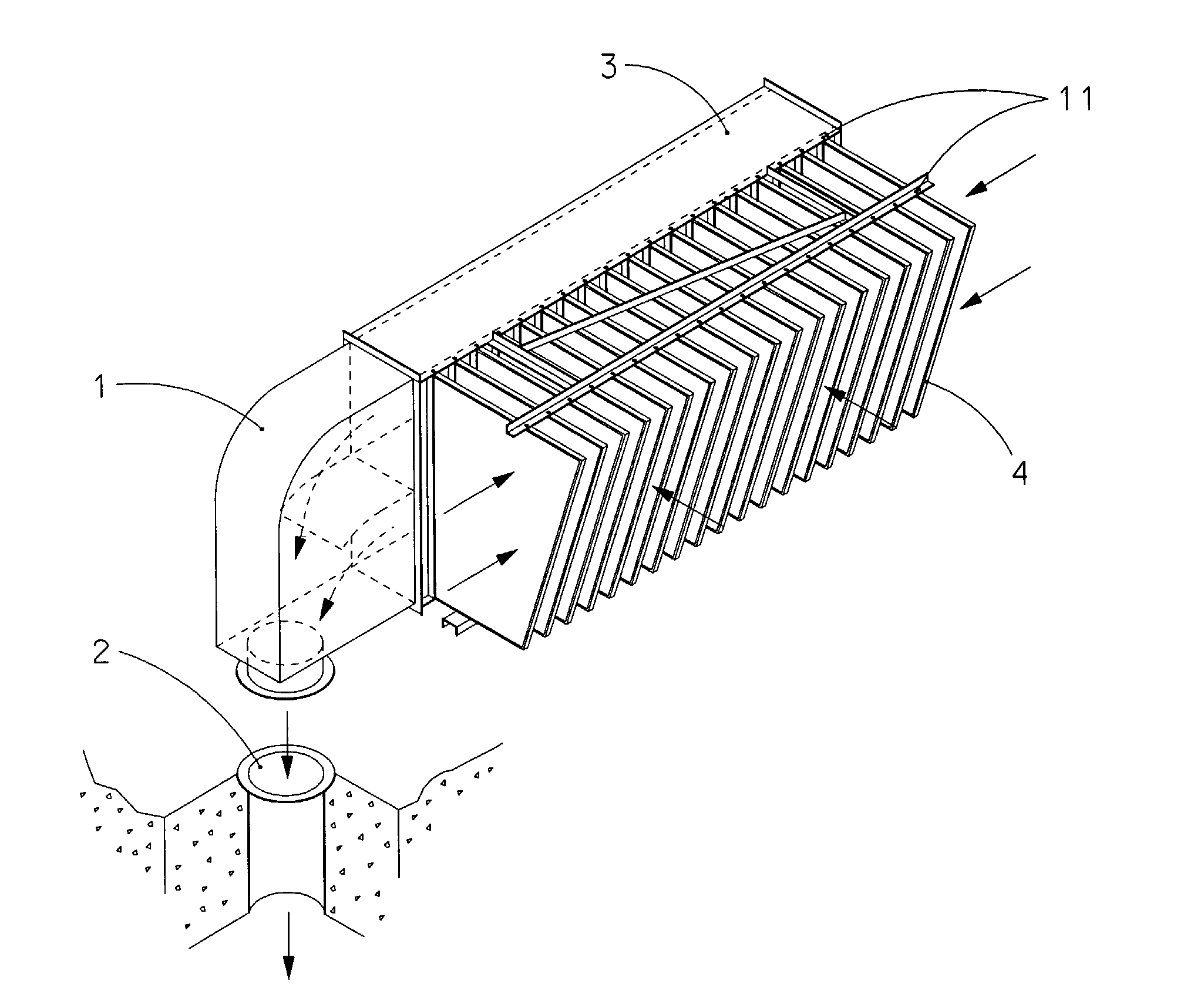
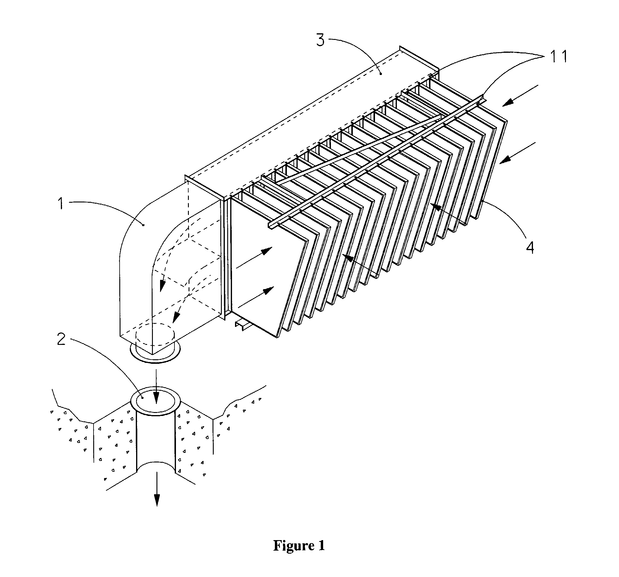
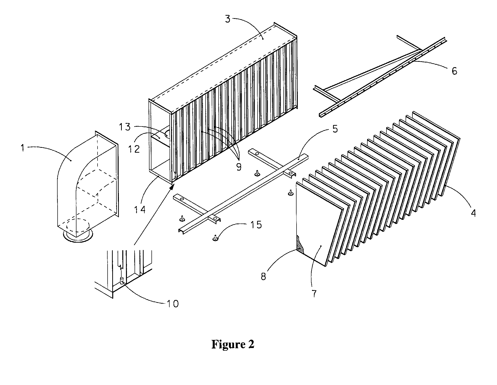
[0019]Referring to FIGS. 1 and 2, the strainer module of the present invention comprises elongated header 3 that defines an internal fluid flowpath that is in fluid communication with a suction source through pump intake pipe 2 which may be located in the floor or wall through one or more connection(s) 1. Header 3 has a generally planar sidewall with a plurality of inlet apertures 9 in the form of a series of substantially parallel elongated slots disposed along the length of the header to accommodate fins 4. The inlet apertures are oriented in a direction transverse to the fluid flowpath within header 3. Strainer elements in the form of hollow flat-surface fins 4 may be mounted on the sides (as shown in FIG. 1), top, or bottom of header 3 and project outwardly from inlet apertures 9. Fins 4 may have a uniform or variable spacing and are located by mounting frames 5 and braces 6. In a preferred embodiment, fins are easily removable, using a pins 10 and bolts 11, but they may also be...


PUM

PropertyMeasurementUnit
Volumeaaaaaaaaaa
Pressure dropaaaaaaaaaa
Permeabilityaaaaaaaaaa

Abstract

The present invention relates to filters used to remove debris from water being sucked into a piping system. It has particular application use in nuclear power plants, which, after a loss of coolant accident, must pump cooling water back into the reactor core from a collection sump. This water may contain various types of debris that must be removed before the water is sent back into the reactor cooling system. There are restrictions on the allowable pressure drop across the strainer and the space available for installing this equipment. The finned strainer of the present invention addresses these issues while maximizing the quantity of debris filtered from the water.

Description

FIELD OF THE INVENTION[0001]The present invention pertains to the field of filters used to remove debris from water being sucked into a piping system. More particularly, the present invention relates to the field of filters used in nuclear power plants.BACKGROUND[0002]Nuclear plants have various safety systems to ensure that the nuclear fuel in the reactor core remains cooled in all credible accident scenarios. One such scenario is a “loss of coolant accident,” in which an external pipe is postulated to break, allowing a large amount of water to escape from the reactor cooling system. This water may dislodge solid debris from neighbouring pipes or other reactor structures. The water, along with some of the dislodged debris, will flow to the lowest parts of the reactor building into a sump. Plants are equipped with safety systems that pump water from the sump back into various reactor cooling systems. Strainers on the pump intakes ensure that any debris large enough to clog equipment...

Claims


Application Information

Patent Timeline
IPC IPC(8): B01D21/30B01D39/10B01D29/07
CPCB01D29/333G21D1/02Y02E30/40B01D29/39B01D35/28B01D35/02Y02E30/30
Inventor RHODES, DAVID BRUCEMCGREGOR, JAMES EDWARD ALLAN
Owner ATOMIC ENERGY OF CANADA LIMITED
Why Eureka
Try Eureka