
Heat dissipation plate of inverter unit fluid radiator

A technology of inverter unit and radiator, which is applied in the direction of modification by conduction heat transfer, cooling/ventilation/heating transformation, etc., which can solve the limitation of the working capacity of heating devices, the difference in heat transfer efficiency of fins, and the low flow rate on the surface of fins, etc. problem, to achieve the effect of reducing variance, good uniformity, and uniform fluid flow rate

Pending Publication Date: 2021-05-14
深圳市法拉第电驱动有限公司
View PDF1 Cites 0 Cited by
  • Summary
  • Abstract
  • Description
  • Claims
  • Application Information

AI Technical Summary

Problems solved by technology

The radiator of this utility model has the following disadvantages: due to factors such as the position of the air inlet, local resistance, etc., even if the fin spacing is uniform, there are differences in flow velocity and pressure in the flow channels between different fins of the radiator; Differences lead to differences in the heat transfer efficiency of different fins, which limits the working capacity of the heating device; even if the flow rate of the flow channels between different fins is the same, when the air flows through the narrow and long flow channels between the fins, a boundary will be formed on the surface of the fins Layer, the deeper the flow channel, the thicker the boundary layer, the lower the flow velocity on the fin surface, and the worse the heat transfer efficiency

Method used


Image

  • Heat dissipation plate of inverter unit fluid radiator
  • Heat dissipation plate of inverter unit fluid radiator
  • Heat dissipation plate of inverter unit fluid radiator

Examples


Embodiment Construction

[0025] The fluid radiator of the inverter unit of the present invention may be an air-cooled radiator or a water-cooled radiator.

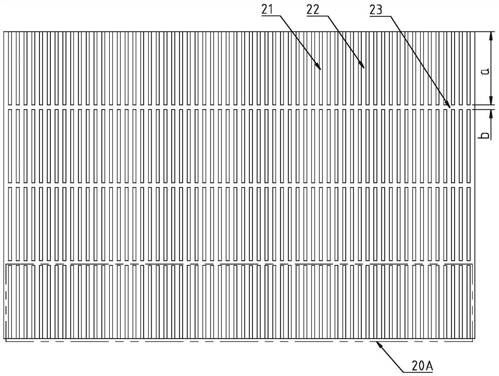
[0026] Embodiment 1 of the present invention The structure of the cooling plate of the water-cooled radiator of the inverter unit is as follows: Figure 1 to Figure 4 As shown, it includes a bottom plate 10 , a heat dissipation portion 20 arranged on the top surface of the top plate, and three horizontally arranged flow equalization grooves 23 . Such as Figure 4 As shown, the heating power device of the inverter unit is installed on the bottom surface of the base plate 10 .

[0027] The heat dissipation part 20 includes 60 fins 21 arranged longitudinally, the gaps between adjacent fins 21 are channels 22 for air flow, and the flow equalization groove 23 runs through the heat dissipation part 20 transversely, dividing the heat dissipation part 20 into four vertically Separate 4 cooling zones 20A. The depth of the flow equalizing groove 23 is eq...


PUM


Abstract

The invention discloses a heat dissipation plate of an inverter unit fluid radiator. The heat dissipation plate comprises a bottom plate, a heat dissipation part arranged on the top surface of the bottom plate and at least one transversely arranged flow equalizing groove, the heat dissipation part comprises a plurality of longitudinally arranged fins, the flow equalizing groove transversely penetrates through the heat dissipation part, and the heat dissipation part is divided into a plurality of longitudinally separated heat dissipation areas. The flow equalizing groove of the heat dissipation plate eliminates the pressure difference between the fins and break the boundary layers on the surfaces of the fins, so that the flow speed of fluid between the fins is uniform, the difference of the heat dissipation capacity of all areas of the heat dissipation device is reduced, and the uniformity of the heat dissipation effect is good.

Description

technical field [0001] The invention relates to a radiator, in particular to a radiator plate for a fluid radiator of an inverter unit. Background technique [0002] The switching tube of the inverter is the heat-generating device of the inverter unit. With the increase of the power density of the inverter, the heat dissipation of the switching tube of the inverter unit is particularly important. The switching tube of the inverter unit usually adopts a fluid radiator for heat dissipation, and the fluid heat dissipation The heat sink of the radiator usually includes a base plate and a plurality of fins fixed on the base plate. [0003] For example, the utility model whose patent number is: CN201520828034.X discloses a fin-embedded friction welding heat sink, including a base plate and fins, and several slots are arranged on the base plate, because the fins are welded by friction welding embedded in the slot. The radiator of this utility model has the following disadvantages...

Claims


Application Information

Patent Timeline
Patent Type & Authority Applications(China)
IPC IPC(8): H05K7/20
CPCH05K7/2039
Inventor 张大千李浩
Owner 深圳市法拉第电驱动有限公司
Learn More