Cart that is Assembled Solidly and Stably

a solid and stab technology, applied in the field of carts, can solve problems such as danger to users, and achieve the effects of solid and stab assembly, not easily loosened or detached, and strengthening the combination strength of the placement boards

Inactive Publication Date: 2008-07-03
NIEH MING HSIAO
View PDF0 Cites 11 Cited by
  • Summary
  • Abstract
  • Description
  • Claims
  • Application Information

AI Technical Summary

Benefits of technology

[0006]The primary objective of the present invention is to provide a cart that is assembled solidly and stably so that the cart is not loosened or detached easily after assembly to provide a safety to a user.
[0007]Another objective of the present invention is to provide a cart, wherein the insertion edge of each of the side plates is inserted into the insertion slot of the support flange of the respective connecting post, and the clamping pieces of each of the side plates are clamped on the stop flanges of each of the placement boards, so that each of the side plates is located between any two of the placement boards and between any two of the connecting posts to reinforce the combination strength of the placement boards and the connecting posts so as to reinforce the structural strength of the cart.
[0008]A further objective of the present invention is to provide a cart, wherein when the connecting posts are mounted between the placement boards, the insert of each of the placement boards is inserted into the insertion hole of the respective connecting post, and each of the limit pieces of each of the placement boards is inserted into the respective limit groove of the respective connecting post by a tapering engagement, so that the connecting posts are combined with the placement boards tightly and closely.
[0009]A further objective of the present invention is to provide a cart, wherein when the handles are mounted on the uppermost one of the placement boards, the mounting groove of each of the handles is mounted on the insert of the uppermost one of the placement boards, and each of the limit slots of each of the handles is mounted on the limit pieces of the uppermost one of the placement boards by a tapering engagement, so that the handles are combined with the uppermost one of the placement boards tightly and closely.

Problems solved by technology

However, each of the connecting posts 80 is mounted in the respective slot 72 of each of the placement boards 70 in a loosely fit manner, so that the connecting posts 80 are easily detached from the placement boards 70 when the placement boards 70 are pulled by the handles 73 to upset the articles placed on the placement boards 70, thereby causing danger to the user.

Method used


Image

  • Cart that is Assembled Solidly and Stably
  • Cart that is Assembled Solidly and Stably
  • Cart that is Assembled Solidly and Stably

Examples


Embodiment Construction

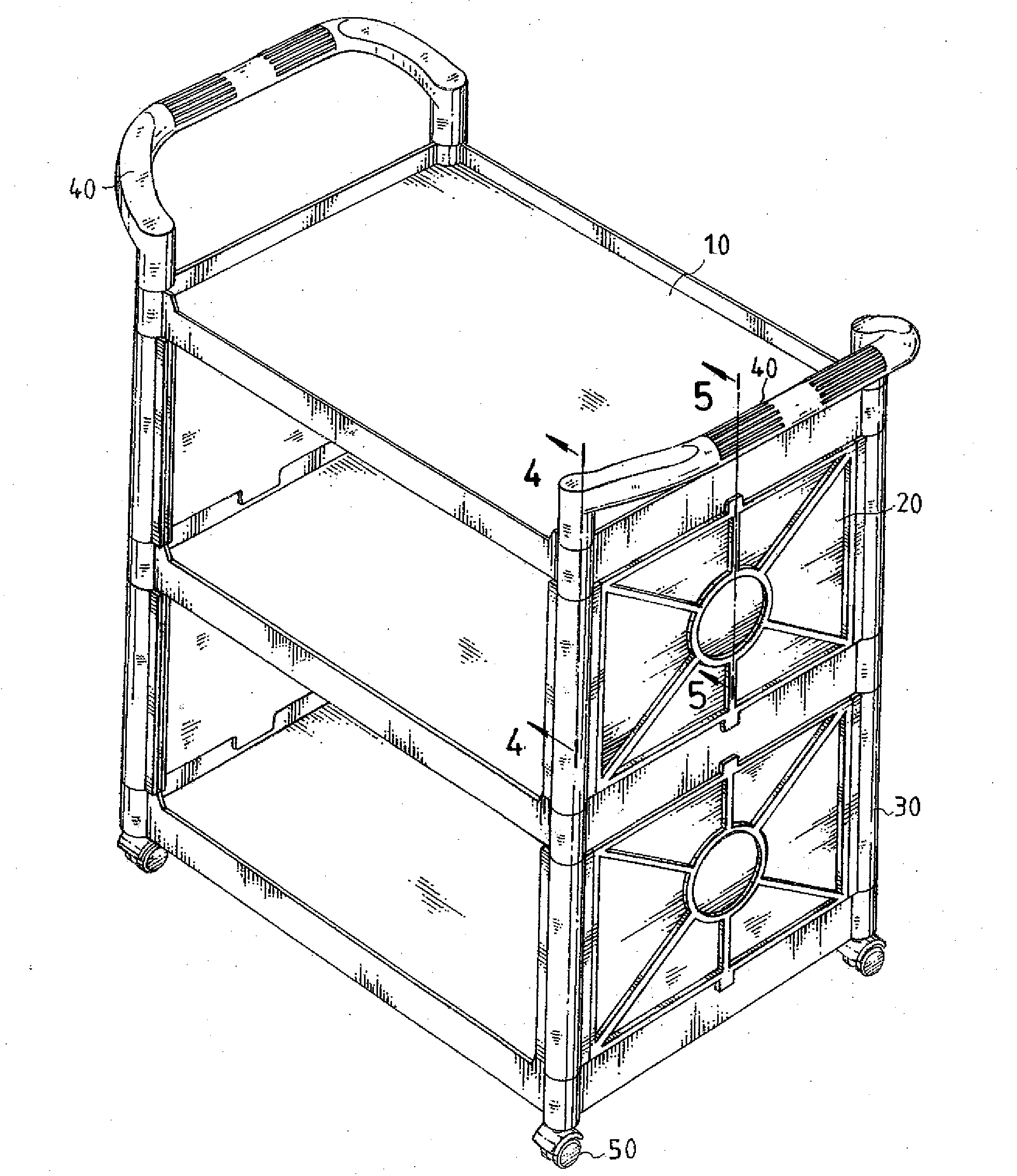
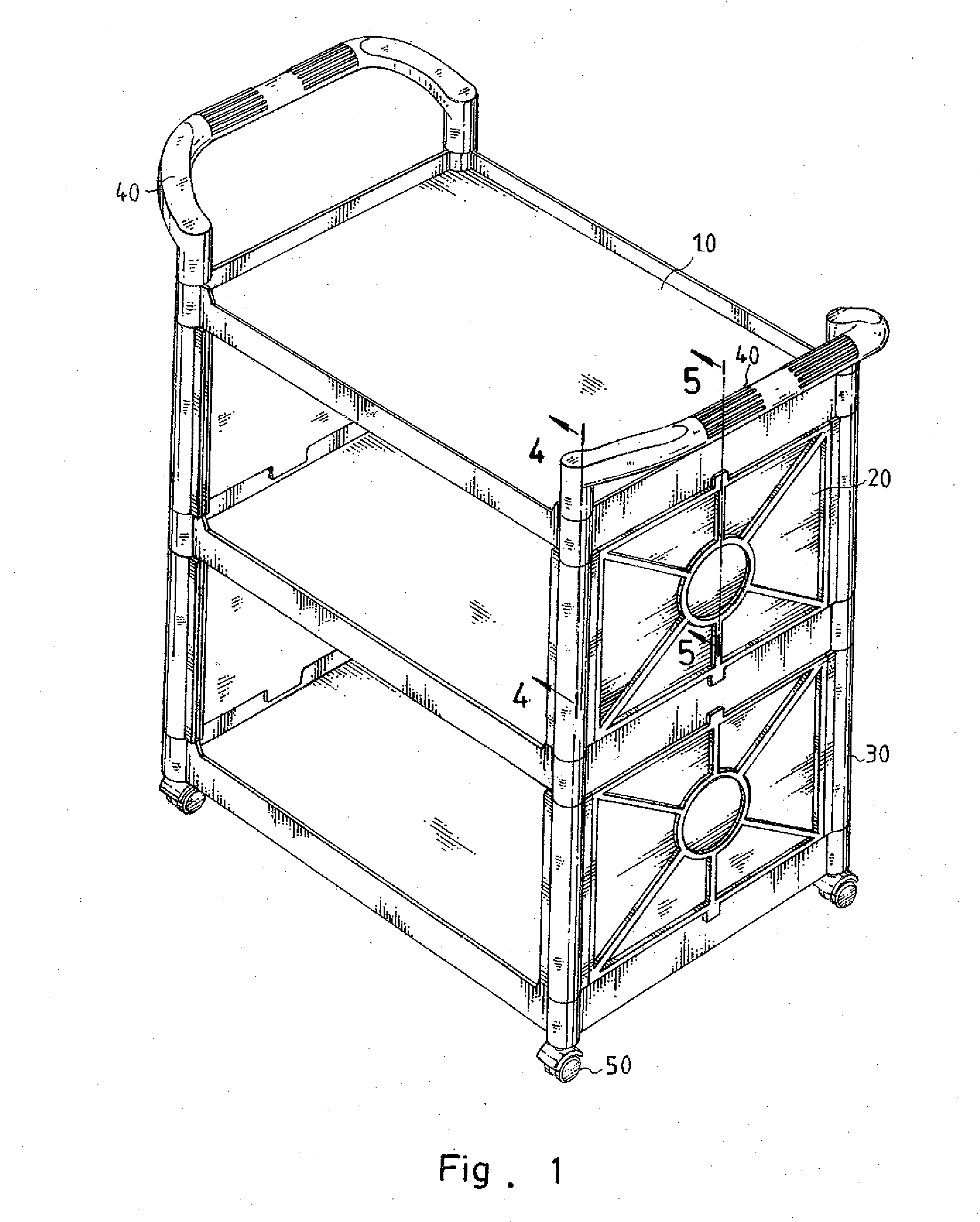
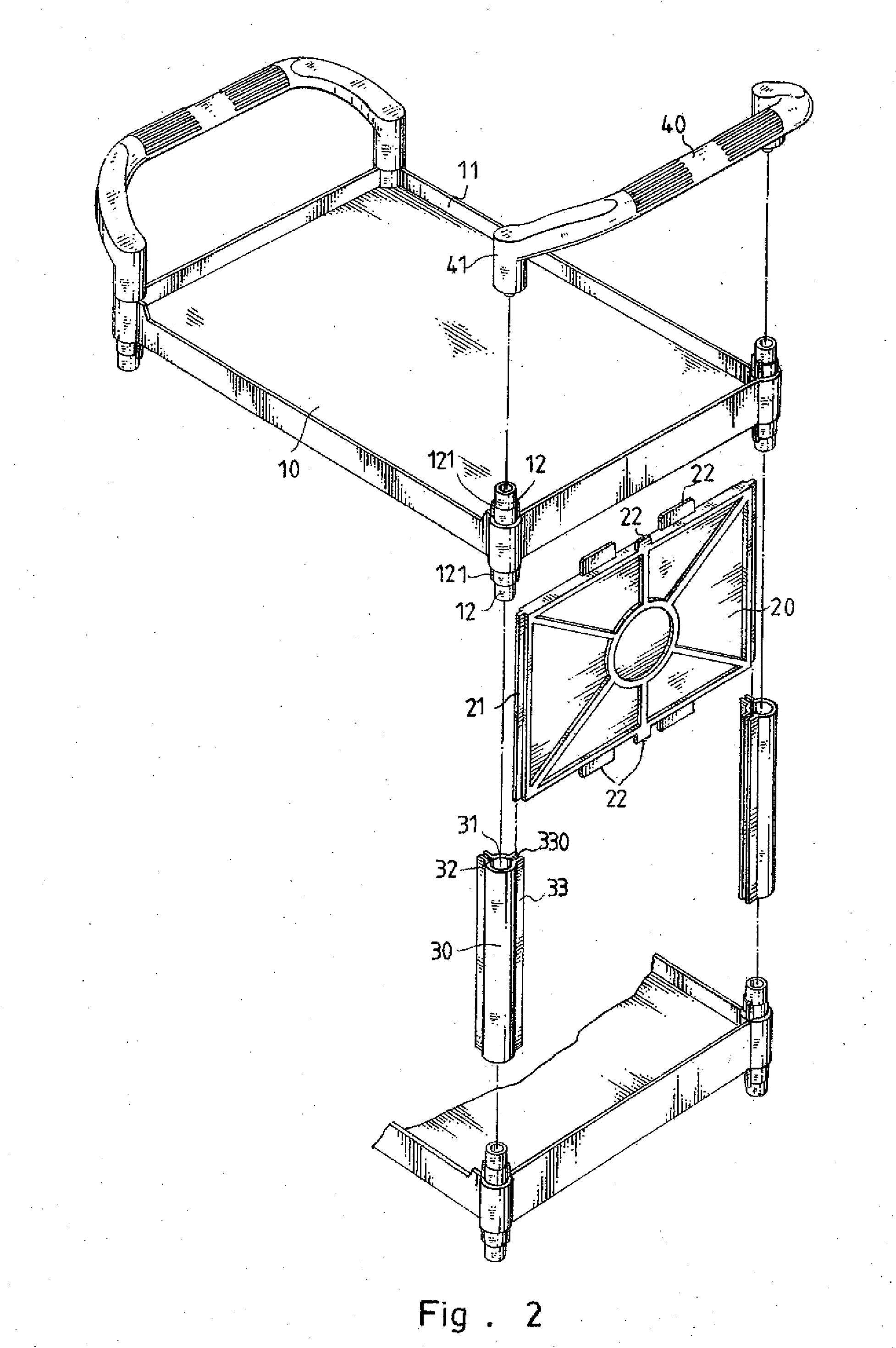
[0021]Referring to the drawings and initially to FIGS. 1-5, a cart in accordance with the preferred embodiment of the present invention comprises a plurality of transverse placement boards 10, a plurality of upright connecting posts 30 mounted between any two of the placement boards 10, a plurality of side plates 20 mounted between any two of the placement boards 10 and located between any two of the connecting posts 30, two handles 40 mounted on an uppermost one of the placement boards 10, and a plurality of castors 50 mounted on a lowermost one of the placement boards 10.

[0022]Each of the connecting posts 30 has a tubular shape and has an inner wall formed with an insertion hole 31 which extends axially through a whole length of each of the connecting posts 30. The insertion hole 31 of each of the connecting posts 30 has a peripheral wall formed with two axially extending limit grooves 32. Each of the limit grooves 32 of each of the connecting posts 30 has a tapered cross-sectiona...


PUM


Abstract

A cart includes a plurality of placement boards, a plurality of connecting posts mounted between the placement boards, a plurality of side plates mounted between the placement boards and the connecting posts, two handles mounted on an uppermost placement board, and a plurality of castors mounted on a lowermost placement board. Thus, each of the side plates is located between any two of the placement boards and between any two of the connecting posts to reinforce the combination strength of the placement boards and the connecting posts so as to reinforce the structural strength of the cart. In addition, the cart is assembled solidly and stably so that the cart is not loosened or detached easily after assembly to provide a safety to a user.

Description

BACKGROUND OF THE INVENTION[0001]1. Field of the Invention[0002]The present invention relates to a cart and, more particularly, to a serving cart for placing dishes or a tool cart for placing hand tools.[0003]2. Description of the Related Art[0004]A conventional cart in accordance with the prior art shown in FIG. 10 comprises a plurality of transverse placement boards 70, a plurality of upright connecting posts 80 mounted between the placement boards 70, two handles 73 mounted on an uppermost one of the placement boards 70, and a plurality of castors (not shown) mounted on a lowermost one of the placement boards 70. Each of the placement boards 70 has a periphery provided with a plurality of protruding stop flanges 71 which extend upward and downward from each of the placement boards 70. Each of the placement boards 70 has a plurality of corners each formed with a slot 72 to allow insertion of a respective connecting post 80. However, each of the connecting posts 80 is mounted in th...

Claims


Application Information

Patent Timeline
Patent Type & Authority Applications(United States)
IPC IPC(8): B62B3/02
CPCB25H3/028B25H3/00
Inventor NIEH, MING-HSIAO
Owner NIEH MING HSIAO
Why Eureka
Try Eureka