
Vehicle Cab Suspension

a technology for suspensions and cabs, applied in mechanical devices, roofs, transportation and packaging, etc., can solve the problems of large shock loads, affecting the performance of suspensions, and requiring maintenance, so as to reduce vary the stiffness of the unit.

Inactive Publication Date: 2008-07-03
BAKSHI NIKESH
View PDF20 Cites 8 Cited by
  • Summary
  • Abstract
  • Description
  • Claims
  • Application Information

AI Technical Summary

Benefits of technology

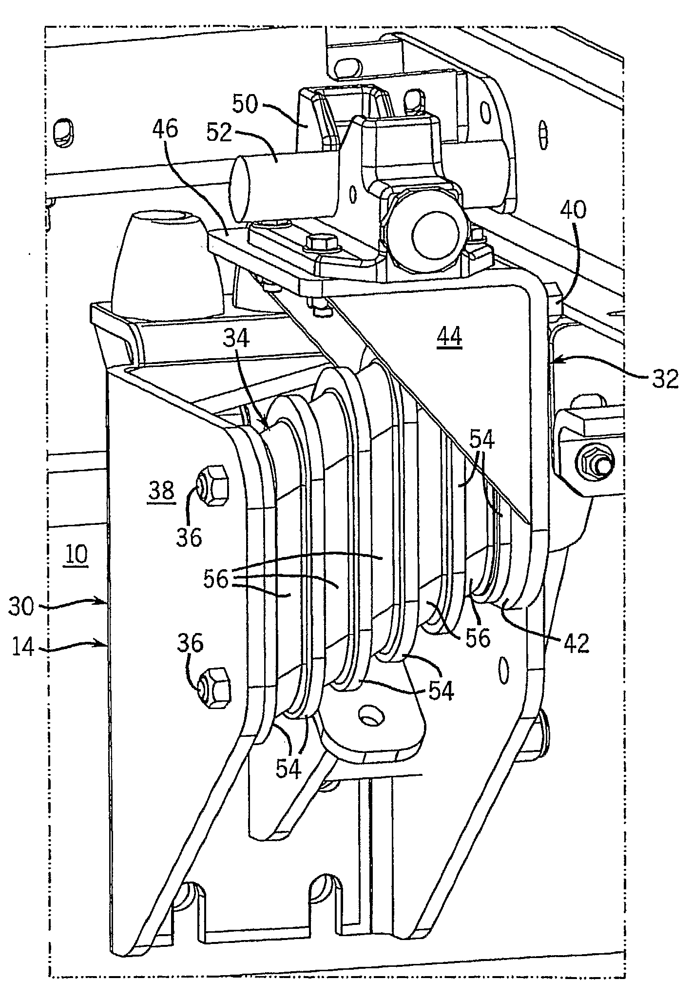
[0009]Also, when the layers are oriented in vertical planes, the layers are subjected to compression from end to end (in the thickness direction of the layers) when the vehicle is stopped due to deceleration forces on the cab, and tension when the vehicle accelerates due to acceleration forces on the cab, which is desirable. The unit can also be arranged so that the layers are subjected to tension upon deceleration or compression upon acceleration, although since deceleration forces tend to be greater than acceleration forces, the former is preferable. The stiffness of the unit in compression and tension along the direction of the thickness of the layers is greater than the stiffness in sheer and therefore the unit is well adapted to counter the acceleration and deceleration forces of the vehicle. In addition, the characteristics of the unit in reaction to acceleration and deceleration forces can be adjusted by changing the angle of the layers to vertical, as described above, reducing its stiffness to acceleration and deceleration forces by increasing the angle between the planes of the layers and a vertical plane.
[0010]In addition, in another feature of the invention, the stiffness of the unit can be varied by varying the thicknesses of the layers. Thicker elastomer layers combined with thinner metal layers, within the same size envelope of the unit, result in a more flexible unit, whereas thinner elastomer layers combined with thicker metal plates results in a stiffer unit. Also, the hardness of the elastomer can be varied to also vary the stiffness.

Problems solved by technology

Such springs, and air springs in particular, and shock absorbers for this application, have required maintenance and been prone to failure as the suspension loads, both in compression and in tension, can be significant.
Such suspensions, particularly the three-point suspensions, can encounter a problem due to twist loading.
In such situations a large shock load can be applied that tends to twist the cab about a longitudinal axis.
This can place a significant load on the air springs and shocks, both in compression and in tension loading, when the suspension rebounds.

Method used


Image

  • Vehicle Cab Suspension
  • Vehicle Cab Suspension
  • Vehicle Cab Suspension

Examples


Embodiment Construction

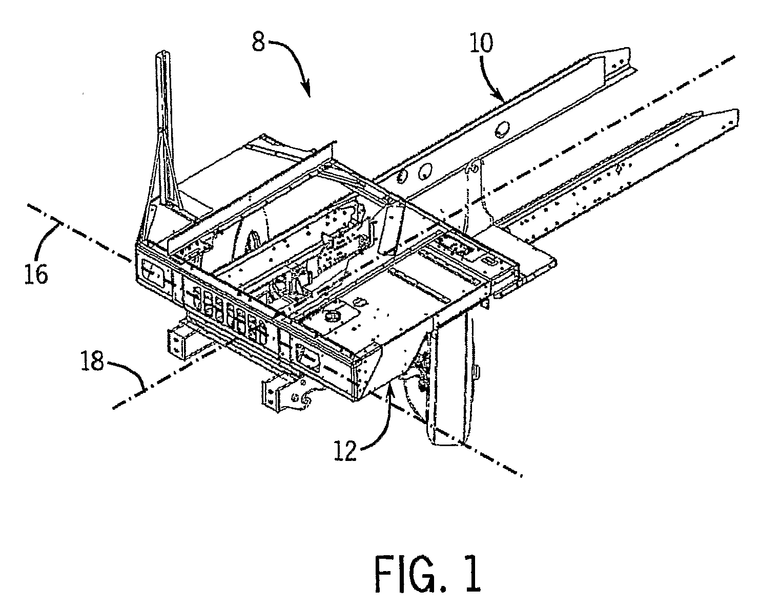
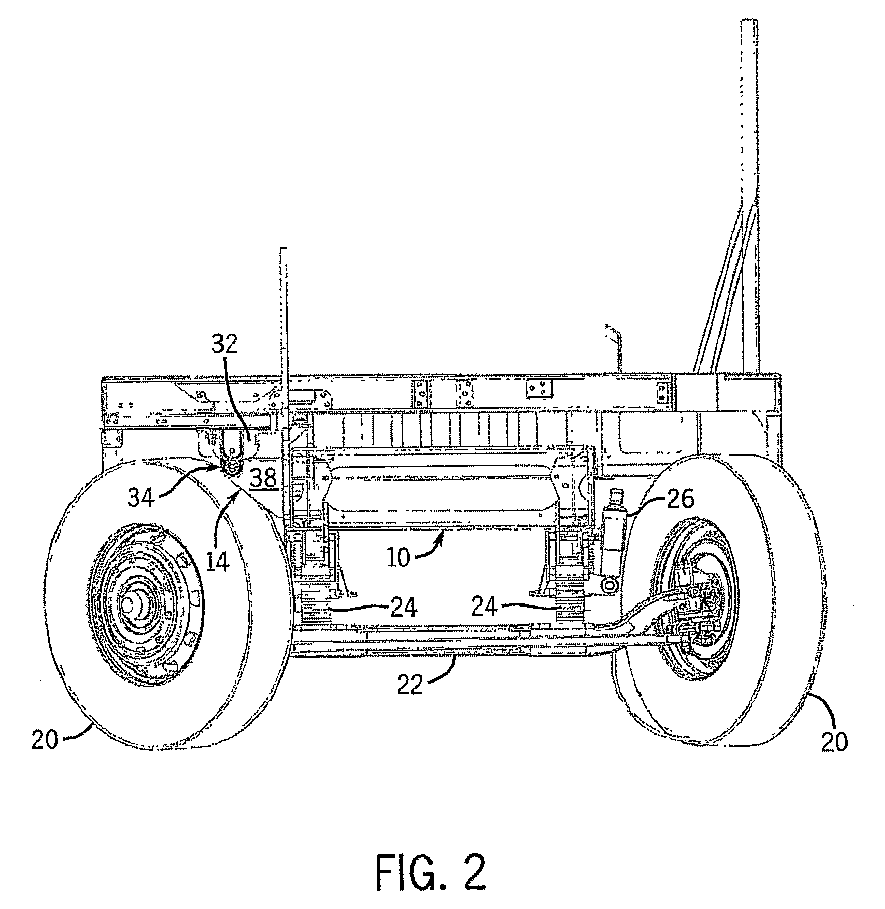
[0018]FIGS. 1-5 illustrate a vehicle 8 including a cab 12 (only the lower portion of which is shown), a chassis 10 and a suspension unit 14 of the invention. The cab 12 is pivotally mounted to the chassis 10 so as to rotate about axis 16 or an axis parallel to axis 16 by any suitable means, which may be conventional. Near the front of the cab 12, the axis 16 runs laterally, being generally horizontal and perpendicular to the direction 18 of normal forward straightline travel of the vehicle 8. The vehicle 8 has ground engaging front wheels 20 (the rear wheels not being shown) that support a beam 22 from which the primary suspension of the vehicle is mounted, the primary suspension including leaf springs 24 and shock absorbers 26 that extend between the beam 22 and the chassis 10. The suspension unit 14 provides a secondary suspension for the cab between the cab 12 and the chassis 10.

[0019]Referring primarily to FIGS. 3-5, the suspension unit 14 includes two brackets 30 and 32 and an ...


PUM


Abstract

A vehicle cab is pivoted to the chassis at the front and supported at the rear by a cab suspension unit that includes a laminate of interleaved elastomer and rigid plate layers. The laminate flexes in reaction to forces that act in the planes of the layers and is relatively resistant to forces that act normal to the layers such that it elastically absorbs shocks and vibrations from road irregularities and pitch and roll maneuvers and more stiffly resists acceleration and deceleration forces between the cab and the chassis.

Description

CROSS-REFERENCE TO RELATED APPLICATION[0001]This claims the benefit of U.S. Provisional Patent Application No. 60 / 679,426 filed May 10, 2005.STATEMENT CONCERNING FEDERALLY SPONSORED RESEARCH OR DEVELOPMENT[0002]Not applicable.FIELD OF THE INVENTION[0003]This invention relates to a suspension for the cab of a vehicle of the type in which the cab is pivoted at the front of the cab to the chassis and has one or more vibration and shock dampening devices between the rear of the cab and the vehicle chassis, and in particular to an elastomeric device for such applications.BACKGROUND OF THE INVENTION[0004]“Cab over” vehicles are well known, in which the truck cab is provided over the engine of the vehicle. In such vehicle constructions, the cab is typically pivoted to the chassis of the vehicle at the front of the cab, about a horizontal axis that runs laterally (perpendicular to the direction of normal straight line vehicle travel). The rear of the truck cab is typically supported with sp...

Claims


Application Information

Patent Timeline
Patent Type & Authority Applications(United States)
IPC IPC(8): B62D24/04
CPCB60G2202/1422F16F1/40B62D33/0604B60G2204/162
Inventor BAKSHI, NIKESH
Owner BAKSHI NIKESH
Learn More