Permanent magnet rotary structure of electric machine

Inactive Publication Date: 2008-07-03
DELTA ELECTRONICS INC
View PDF11 Cites 39 Cited by
  • Summary
  • Abstract
  • Description
  • Claims
  • Application Information

AI Technical Summary

Benefits of technology

[0017]It is therefore an object of the present invention to propose a permanent ma

Problems solved by technology

The issues raised by the cogging torque are the variation of the output torque of the electric machine such that the smooth operation of the electric machine is influenced, and the speed of the motor becomes unstable and the noise and vibration are thus generated.
Although the rotary structure of a conventional outer rotor permanent magnet mo

Method used


Image

  • Permanent magnet rotary structure of electric machine
  • Permanent magnet rotary structure of electric machine
  • Permanent magnet rotary structure of electric machine

Examples


first embodiment

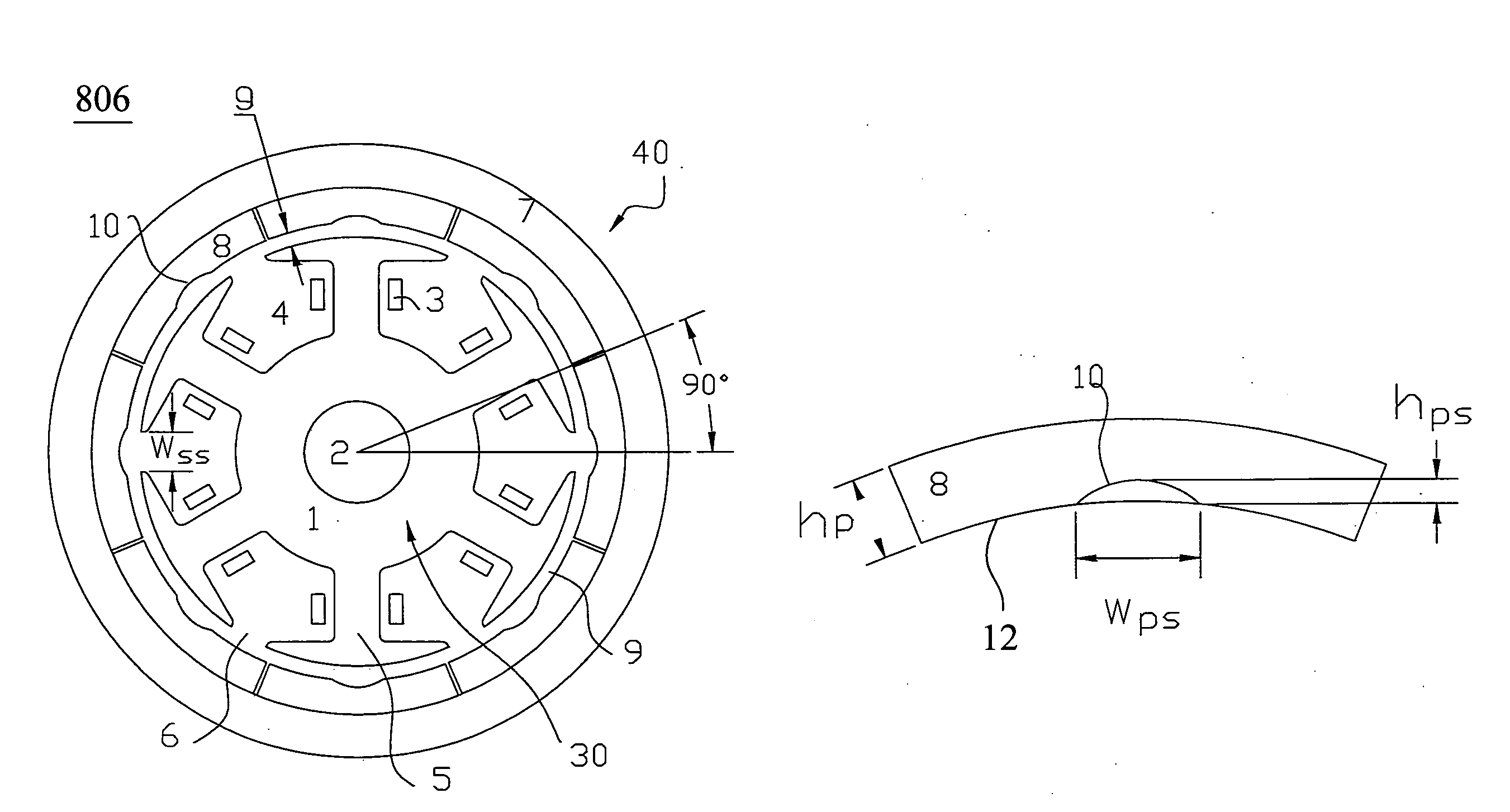
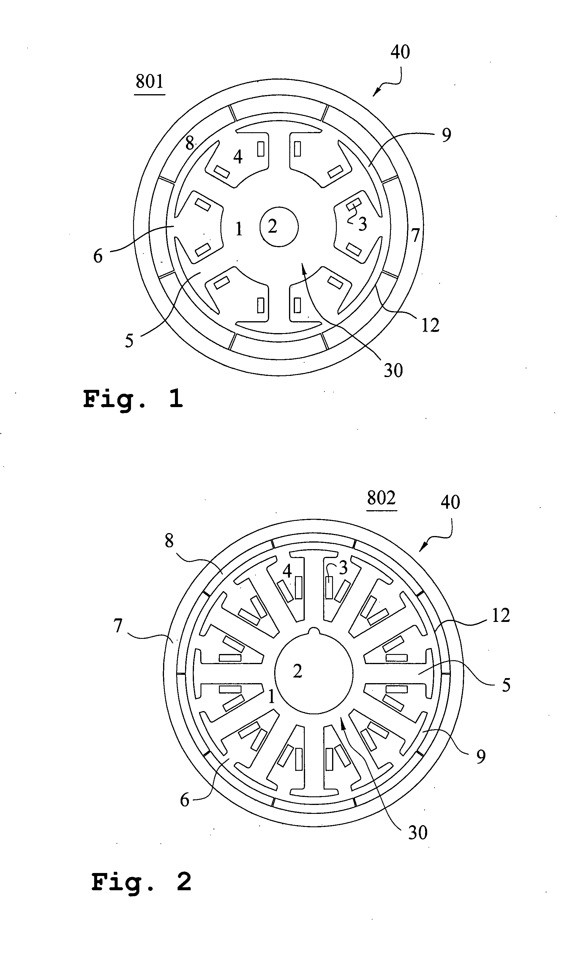
[0063]Subsequently, a preferred embodiment of the present invention is presented as follows to demonstrate the preceding principle. Please refer to FIG. 6, which is a cross-sectional view illustrating the first embodiment regarding the rotary structure of a permanent magnet motor for the present application. The rotary structure 806 of the permanent magnet motor in FIG. 6 is based on the outer rotor permanent magnet motor illustrating in FIG. 1 but the structure for decreasing the cogging torque is further incorporated thereinto. The rotary structure 806 is a permanent magnet motor with eight poles and six slots, but it is not limited to the permanent magnet motor, and the same structure is also applicable to the permanent magnet generator. In FIG. 6, the rotary structure 806 of the permanent magnet motor includes a stator 30 and a rotor 40, in which the cylindrical stator 30 is fixed inside the inner space of permanent magnet motor in order to produce a rotating magnetic field. The...

second embodiment

[0067]Furthermore, a permanent magnet motor with ten poles and twelve slots is presented as an example for addressing the reduction of the cogging torque. Please refer to FIG. 7, which is a cross-sectional view illustrating the second embodiment regarding the rotary structure of a permanent magnet motor for the present application. The rotary structure 807 of the permanent magnet motor in FIG. 7 is based on the outer rotor permanent magnet motor illustrating in FIG. 2 but the structure for decreasing the cogging torque is further incorporated thereinto. Both FIGS. 2 and 7 share the same reference numerals for addressing the identical element. In order to reduce the cogging torque, at least one groove 10 is disposed at the arc surface 12 along the circumference direction of each permanent magnet 8 in FIG. 7. The structure demonstrated in this preferred embodiment is defined as follows: follows: P=5, K=12, M=60 and f=60. After calculating, it is understood that the preferred angular p...

third embodiment

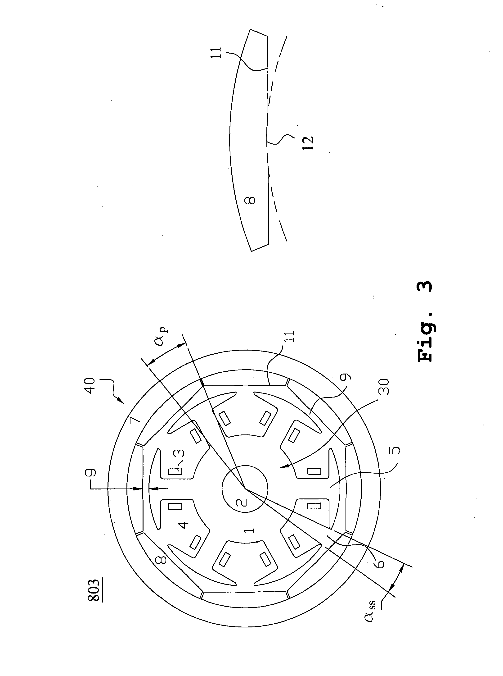
[0083]Subsequently, a preferred embodiment of the present invention is presented as follows to demonstrate the preceding principle. Please refer to FIG. 8, which is a cross-sectional view illustrating the third embodiment regarding the rotary structure of a permanent magnet motor for the present application. The rotary structure 808 of the permanent magnet motor in FIG. 8 is based on the outer rotor permanent magnet motor illustrating in FIG. 3 but the structure for reducing the cogging torque is further incorporated thereinto. Both figures share the same reference numerals for addressing the identical element. In the present preferred embodiment, the relevant computing parameters are defined as follows: P=4, K=6, M=24 and f=24. In accordance with step (q), calculating and choosing an angle, αp, along the circumference direction within an angular range for each angular range corresponding to the pair of the arc-cut surface 11 of the permanent magnets 8. The phase difference, α0, bet...


PUM


Abstract

A permanent magnet motor is provided. The permanent magnet motor includes a stator having a stator shaft having an outer surface, K salient teeth formed upon the outer surface, and K winding slots formed among the K salient teeth, and a rotor having a first inner surface facing the outer surface, and P pairs of permanent magnets formed on the first inner surface, each of which has a second inner surface facing the outer surface and at least a groove formed on the second inner surface to reduce a cogging torque.

Description

FIELD OF THE INVENTION[0001]The present invention relates to a rotary structure of a permanent magnet motor, in particular, to a rotary structure applied in a brushless motor permanent magnet motor so as to reduce the cogging torque.BACKGROUND OF THE INVENTION[0002]There are several advantages as follows that the permanent magnet motor possesses such as: the simplified structure, the reliable motion, the small volume, the light weight, the lower losses and the highly efficiency etc. Furthermore, the shape and the size of the motor are easily variable such that it is wildly applicable to the field of the aviation industry, the national defense, the industry, the agriculture and the respective field in the daily life.[0003]Please referring to FIG. 1, which is a cross-sectional view illustrating the rotary structure of a conventional outer rotor permanent magnet motor, in which a permanent magnet motor with eight poles and six slots is presented as an example for addressing the rotary ...

Claims


Application Information

Patent Timeline
IPC IPC(8): H02K21/22
CPCH02K29/03H02K1/2786H02K1/2791
Inventor WU, LIJIANJIN, WANBINGYING, JIANPINGHUANG, SHIH-MINGHUANG, WEN-SHI
Owner DELTA ELECTRONICS INC
Why Eureka
Try Eureka