Image warping and lateral color correction

a color correction and image technology, applied in the field of display system and image production, can solve the problems of combined distortion of displayed image, low quality or indelicate optics, and geometric distortion of produced imag

Inactive Publication Date: 2008-07-03
TEXAS INSTR INC
View PDF2 Cites 162 Cited by
  • Summary
  • Abstract
  • Description
  • Claims
  • Application Information

AI Technical Summary

Problems solved by technology

Low quality or indelicate optics may introduce geometric distortions in produced images.
When superimposed to form the desired image, distortions in different color image components are mixed together—resulting in combined distortion in the displayed image.

Method used


Image

  • Image warping and lateral color correction
  • Image warping and lateral color correction
  • Image warping and lateral color correction

Examples


Embodiment Construction

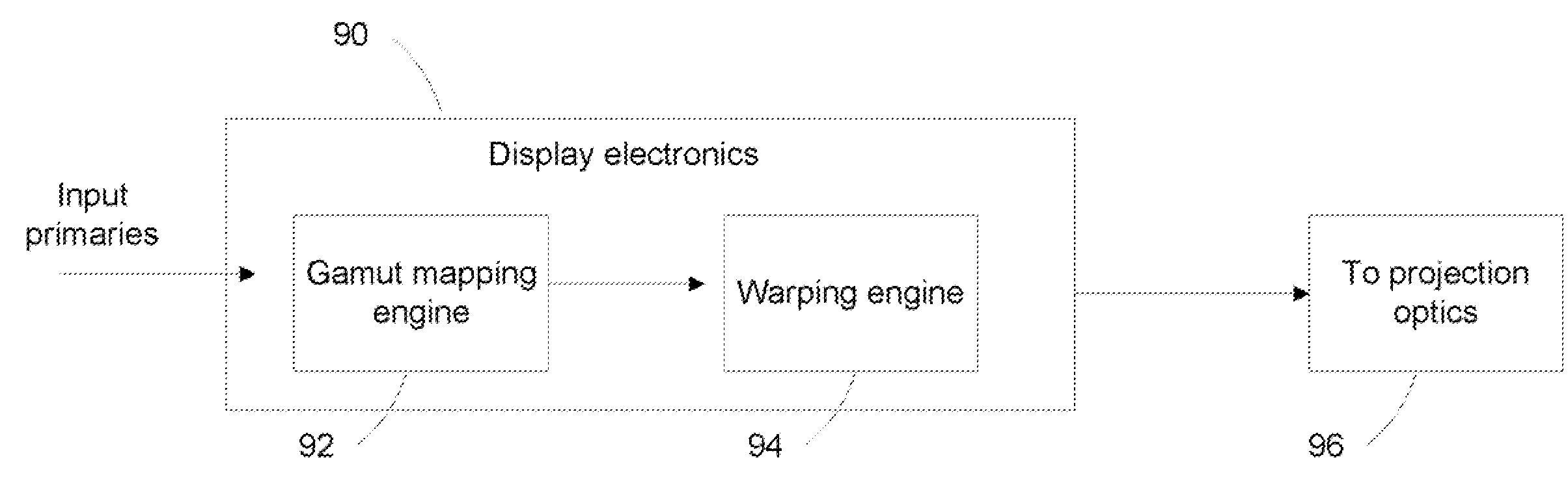
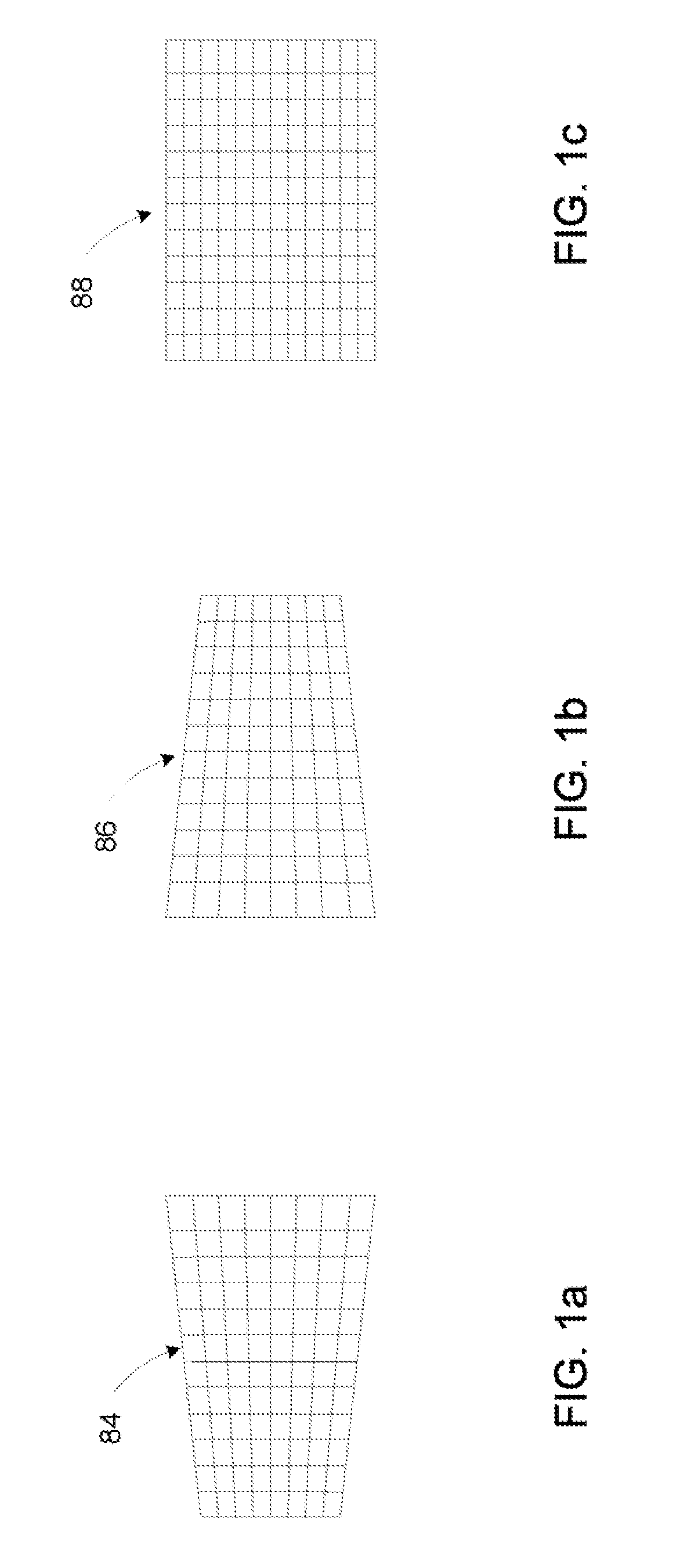
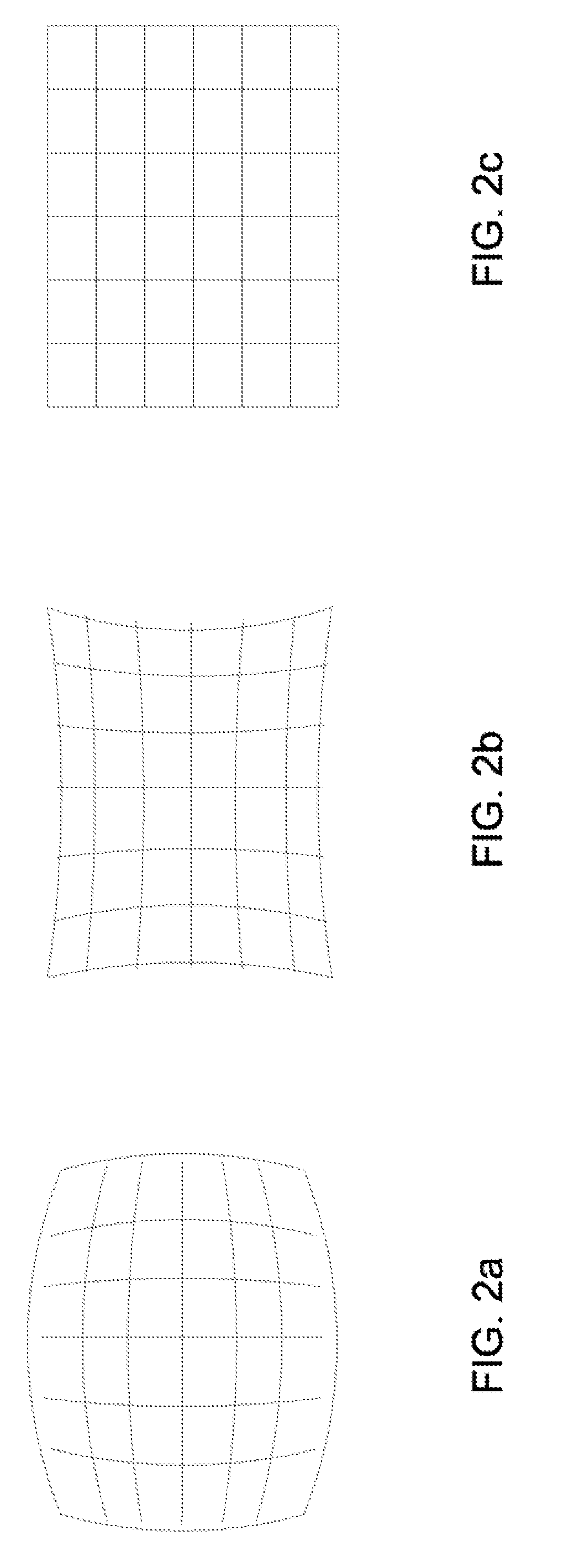
[0011]Disclosed herein is a method for correcting geometric distortions introduced by optical elements of the display system used for reproducing the image with the correction being performed on distortions in individual color image component.

[0012]Unlike existing image correction solutions that either assume that the geometric distortion is the same for each primary color image component, or that the input and output primary colors perfectly match, the method disclosed herein corrects the distortion for each color image component used in the display system to display the image. Specifically, the distortion in each color image component introduced by the display system used for reproducing the image having the color component is analyzed and characterized. Corresponding to the distorted color image component with the characterized distortion, a pre-distorted correction color image component is generated. Such correction color image component has an opposite distortion that is comple...


PUM


Abstract

Color or grayscale images having optical elements induced geometric distortions can be corrected on individual color image component by creating correction image component having the complementary distortion; and applying the correction image component to the corresponding distorted color image component.

Description

TECHNICAL FIELD[0001]The technical field of the examples to be disclosed in the following sections relates to the art of display systems and image production, and more particularly, to the art of image processing in display production.BACKGROUND[0002]Optics is the key element in current display systems. Low quality or indelicate optics may introduce geometric distortions in produced images. In display systems using a set of elementary colors (i.e. primary colors) to present desired color images, each elementary color image component may have separate distortions; while different color image components may have different distortions. When superimposed to form the desired image, distortions in different color image components are mixed together—resulting in combined distortion in the displayed image.SUMMARY[0003]In one example, a method for producing an image using an image producing system is disclosed herein. The method comprises: characterizing a geometric distortion introduced to ...

Claims


Application Information

Patent Timeline
Patent Type & Authority Applications(United States)
IPC IPC(8): G09G5/00
CPCG02B27/0025G09G5/02G09G3/001
Inventor KEMPF, JEFFREY MATTHEWRAMANATH, RAJEEVLIEB, DAVID FOSTERNEAL, HENRY W.SKOOG, ARNOLD P.
Owner TEXAS INSTR INC
Why Eureka
Try Eureka