Ink jet recording apparatus, ink supplying mechanism and ink jet recording method

a technology of ink jet and recording apparatus, which is applied in the direction of printing, etc., can solve the problems of difficult to secure the diameter of the duct, the most likely long and meandering ink duct of the printing machine, and the mechanical limitation of the printing machine in supplying

Inactive Publication Date: 2008-07-03
TOSHIBA TEC KK
View PDF5 Cites 32 Cited by
  • Summary
  • Abstract
  • Description
  • Claims
  • Application Information

AI Technical Summary

Benefits of technology

[0010]An ink jet recording apparatus according to an embodiment of the invention includes: an ink jet head having a pressure chamber with a nozzle, an upstream port and a downstream port; a main tank connected to the ink jet head via the upstream port and capable of holding ink therein; and a sub-tank connected to the ink jet head via the downstream port and capable of storing ink therein. At least when printing by ejecting ink from the nozzle, the relation between ph, r, R and Q is held to satisfy ph−{QR×(1 / (1+r))}=Pn (Pn being a constant representing a proper pressure in the nozzle), where ph represents a potential pressure in the main tank as viewed from the nozzle of the ink jet head, R represents a total flow path resistance from the main tank to the sub-tank via the ink jet head, a ratio of a flow path resistance from the main tank to the nozzle and a flow path resistance from the nozzle to the sub-tank is expressed by 1:r, and Q represents a flow rate of ink that circulates in a circulation path formed by connecting the ink jet head, the main tank and the sub-tank.

Problems solved by technology

However, there often is a mechanical limitation of a printing machine in supplying the ink from the position below the head as described above.
If ink is to be fed to the head from the ink tank situated below the head in such a printing machine, the ink duct is most likely to be long and meandering.
Therefore, it is also difficult to secure the diameter of the duct.
Therefore, the negative pressure in the pressure chamber near the nozzle is changed by the quantity of ejected ink affected by the flow path resistance, and it becomes difficult to maintain a proper negative pressure.
Also, a long and meandering duct complicates the structure of the printing machine and causes poor maintainability.
Since the ink volume in the duct is large, waste of ink increases.
However, with these mechanisms, it is difficult to secure compatibility with various types of ink.
Also, no idea is given of applying this technique to an ink supply system of a circulation-type head.

Method used


Image

  • Ink jet recording apparatus, ink supplying mechanism and ink jet recording method
  • Ink jet recording apparatus, ink supplying mechanism and ink jet recording method
  • Ink jet recording apparatus, ink supplying mechanism and ink jet recording method

Examples


first embodiment

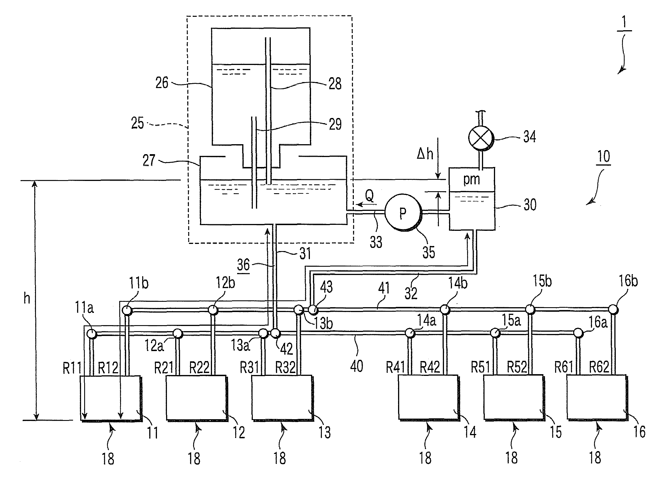
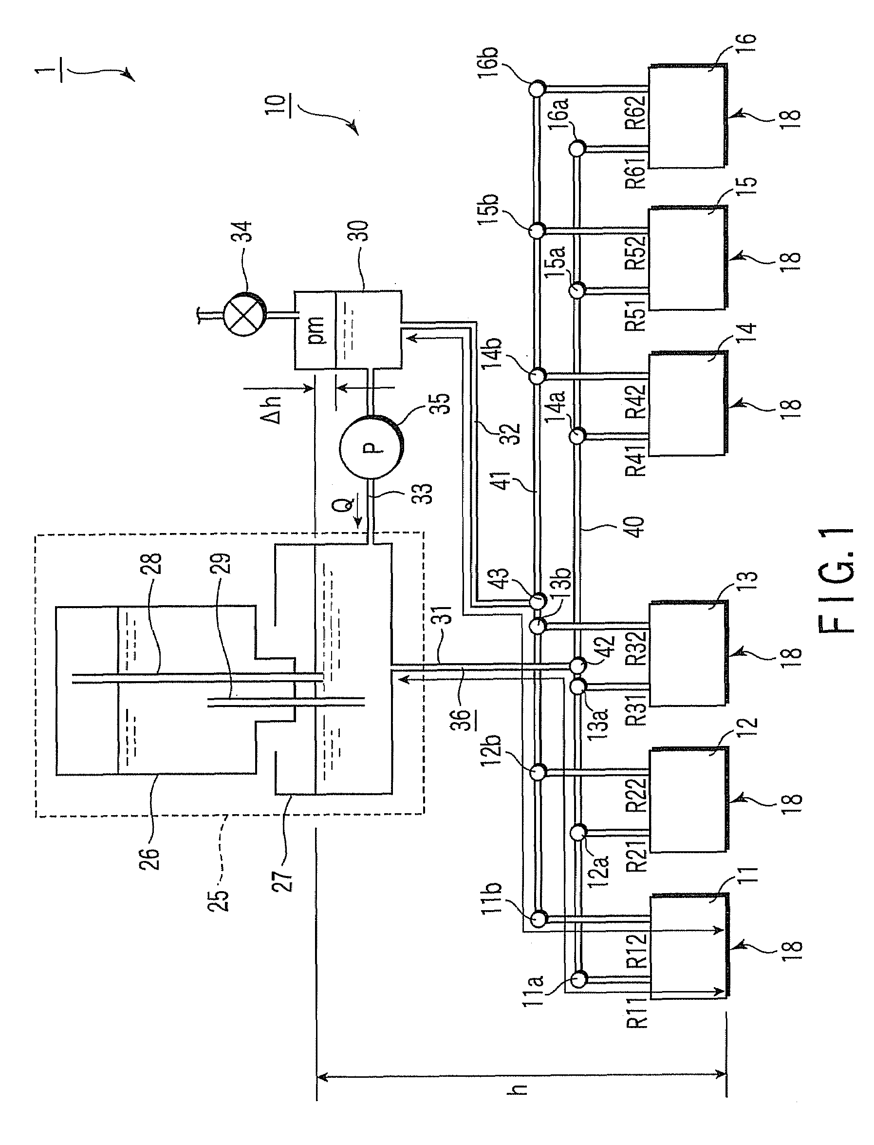
[0025]Hereinafter, an ink jet recording apparatus and ink jet recording method according to an embodiment of the invention will be described with reference to FIG. 1 to FIG. 3. In the drawings, the configuration is schematically shown in an enlarged or reduced manner, or with some parts omitted. An ink jet recording apparatus 1 is configured to form an image by ejecting ink onto a recording medium, not shown, from nozzles of ink jet heads 11 to 16 while circulating the ink. It has an ink supplying mechanism 10. This ink supplying mechanism 10 has plural (in this case, six) ink jet heads 11 to 16, a main tank 25 as an ink supply tank, a negative-pressure tank 30 for storing ink, first, second and third ducts 31 to 33 that connect these and form an ink circulation path, a circulation pump 35 as an ink feed mechanism to circulate ink, and so on.

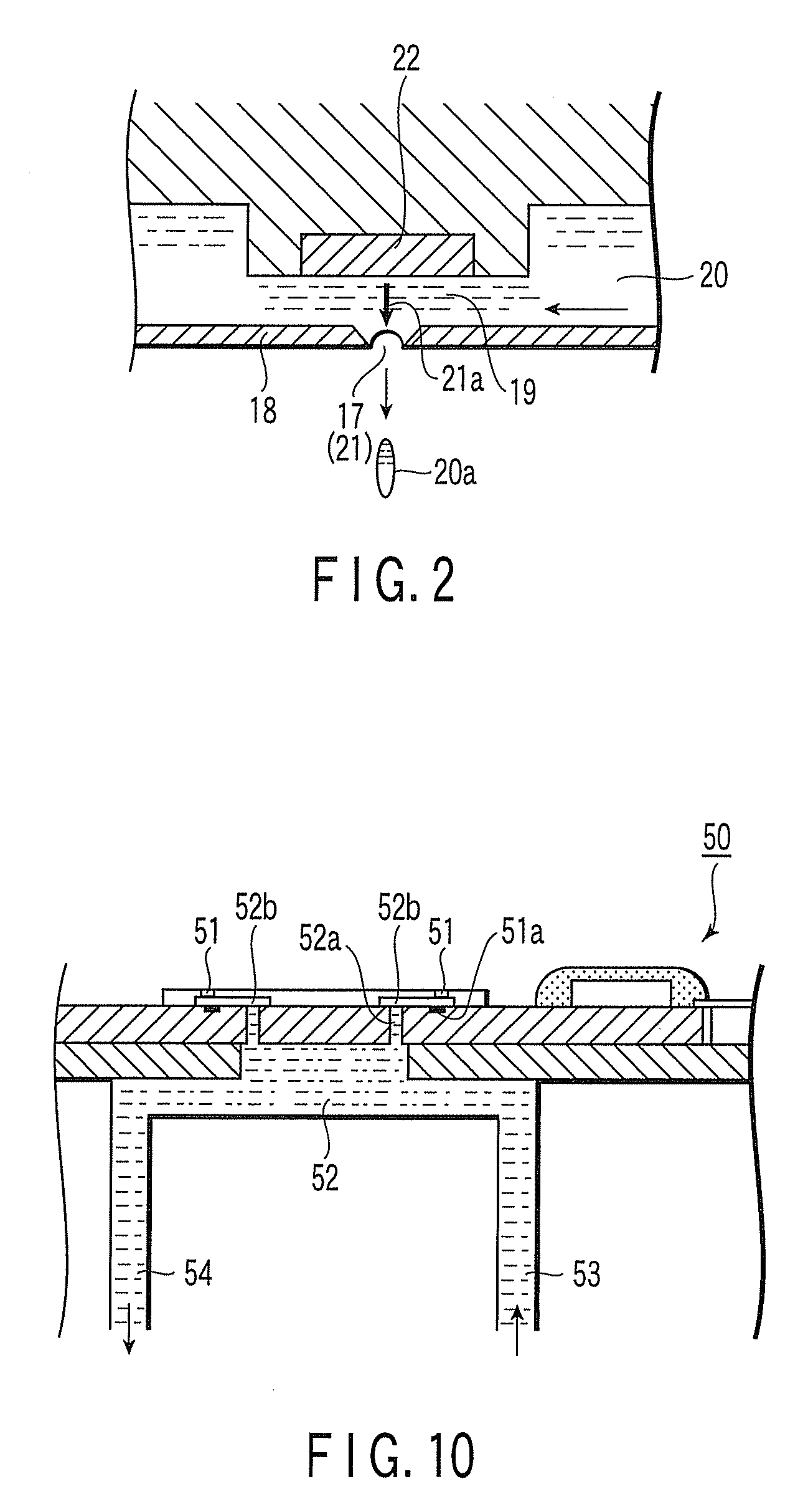
[0026]Each of the ink jet heads 11 to 16 shown in FIG. 2 has an orifice plate 18 having a nozzle 17. A pressure chamber 19 facing the nozzle 17...

second embodiment

[0060]Next, an ink jet recording apparatus and an ink jet recording method according to a second embodiment of the invention will be described with reference to FIG. 4. The configuration is similar to that of the first embodiment except for the value of the ratio r of flow path resistance, and therefore will not be described further.

[0061]In an ink jet recording apparatus 2 according to this embodiment, the flow path resistance in each part on the upstream of the nozzle 17 is set to be smaller than in the first embodiment, and the flow path resistance in each part on the downstream is set to be larger than in the first embodiment. The value of the ratio r of flow path resistance is 2. If the flow path resistance R as viewed from the two points of the main tank 25 and the negative-pressure tank 30 is the same as in the first embodiment, the circulation flow rate Q that can maintain the pressure in the nozzle 17 at the same proper value in the first embodiment is Q=1500 / (6.7×108×(1 / (1...

third embodiment

[0066]Next, an ink jet recording apparatus and an ink jet recording method according to a third embodiment of the invention will be described with reference to FIG. 5. The configuration is similar to that of the first embodiment except for the value of the ratio r of flow path resistance, and therefore will not be described further.

[0067]In an ink jet recording apparatus 3 according to this embodiment, the flow path resistance in each part on the upstream of the nozzle 17 is set to be larger than in the first embodiment, and the flow path resistance in each part on the downstream is set to be smaller than in the first embodiment. The value of the ratio r of flow path resistance is 0.5. Here, a case where the flow path resistance R as viewed from the two points of the main tank 25 and the negative-pressure tank 30 is the same as in the first embodiment will be described. The circulation flow rate Q that can maintain the nozzle pressure at the same proper value in the first embodiment...


PUM


Abstract

An ink jet recording apparatus according to an embodiment of the invention includes an ink jet head having a pressure chamber facing a nozzle, and an upstream port and a downstream port connected to the pressure chamber, a main tank connected to the ink jet head via the upstream port and capable of storing ink therein, and a sub-tank connected to the ink jet head via the downstream port and capable of storing ink, wherein at least when printing by ejecting ink from the nozzle, the relation between ph, r, R and Q is held to satisfy ph−{QR×(1/(1+r))}=Pn (Pn being a constant representing a proper pressure in the nozzle), where ph represents a potential pressure in the main tank as viewed from a surface of an orifice plate where the nozzle of the ink jet head is formed, R represents a total flow path resistance from the main tank to the sub-tank via the ink jet head, a ratio of a flow path resistance from the main tank to the nozzle and a flow path resistance from the nozzle to the sub-tank is expressed by 1:r, and Q represents a flow rate of ink that circulates in a circulation path formed by connecting the ink jet head, the main tank and the sub-tank.

Description

BACKGROUND OF THE INVENTION[0001]1. Field of the Invention[0002]The present invention relates to an ink jet recording apparatus, an ink supplying mechanism and an ink jet recording method in which ink is ejected from an ink jet head while the ink is circulated.[0003]2. Description of the Related Art[0004]An ink jet recording apparatus and an ink jet recording method have been known in which ink is ejected from a nozzle of an ink jet head while the ink is circulated. In such an ink jet recording apparatus, leakage of the ink from the nozzle and suction of air from the nozzle are prevented and a proper ejection droplet shape of the ink must be provided. To realize these, it is considered desirable that the pressure near the nozzle of the ink jet head should be maintained at a proper value. For example, in an ink jet recording apparatus as shown in FIG. 11, the ink tank is arranged below the head in order to realize a negative pressure near the nozzle. The head is connected to a lower ...

Claims


Application Information

Patent Timeline
Patent Type & Authority Applications(United States)
IPC IPC(8): B41J2/18
CPCB41J2/175B41J2/18B41J2/17509
Inventor NITTA, NOBORUSHIMOSATO, MASASHINISHIDA, HIDEAKISUZUKI, ISAO
Owner TOSHIBA TEC KK
Why Eureka
Try Eureka