Inkjet recording head and inkjet recording apparatus

a recording head and inkjet technology, applied in the direction of printing, other printing apparatus, etc., can solve the problems of difficult to achieve ink discharge, long drying time of ink, and deterioration of printed image quality, so as to prevent the occurrence of nozzle blockage and prevent the increase in the viscosity of ink at the meniscus surfa

Inactive Publication Date: 2008-08-12
FUJIFILM CORP
View PDF22 Cites 34 Cited by
  • Summary
  • Abstract
  • Description
  • Claims
  • Application Information

AI Technical Summary

Benefits of technology

[0019]The present invention has been made in view of foregoing circumstances, and it is an object of the present invention to prevent the nozzle blockage. Another object of the present invention is to provide an inkjet recording apparatus using a radiation-curable ink, such as ultraviolet-curable ink, which can prevent the occurrence of the nozzle blockage caused by hardening the radiation-curable ink inside the nozzle due to the scattering of the light irradiated onto the discharged ink in order to harden the discharged ink. Another object of the present invention is to provide an inkjet recording head and an inkjet recording apparatus that can prevent increase in viscosity of the liquid at the meniscus surface by constantly supplying liquid to the meniscus surface.

Problems solved by technology

Hence, if the viscosity of the ink increases or the ink hardens due to the evaporation of the solvent or the like, then blocking of the nozzles may occur and it may become difficult to achieve the ink discharge.
If ink of this kind is used, then when printing onto a record paper of low permeability is performed, the ink takes a long time to dry.
Hence, the bleeding and color mixture of the ink may arise and a printed surface being still wet may touch components of the main unit of the printer, consequently, the printed image may deteriorate in quality.
However, adverse effects on ink discharge and ink composition may result because the ink droplets make contact with the sealing liquid when they are discharged from the nozzles onto the recording medium.
Hence, at the meniscus surface of the ink in the vicinity of the opening section of the nozzle, the solvent in the ink is liable to evaporate and hence the ink is liable to increase in viscosity.
If the ink at the meniscus surface reaches a state of increased viscosity, then this may incur the discharge defects of the nozzles.
If the evaporation continues further, then the ink component becomes a film-like form at the meniscus surface, and thereby it incurs discharge defects that are even harder to recover.
When a state of this kind occurs, it is difficult to discharge ink from the nozzle and hence discharge defects of the nozzles may occur.
However, while the refresh operation is effective in preventing discharge defects in nozzles due to the ink with increased viscosity in the vicinity of the meniscus surface, the refresh operation requires consuming ink wastefully.
Moreover, printing cannot be carried out during the refresh operation, and hence printing speed is reduced.
If the number of refresh operations is lowered in order to maintain printing speed, then it may be difficult to satisfactorily prevent the increased viscosity of the ink at the meniscus surface.
This method is able to suppress the wasteful consumption of ink, but it requires control for vibrating the meniscus surface and may be inherently unsuited to prevent the discharge defects.
However, if the light source is positioned close to the nozzle, then the luminous energy of scattered ultraviolet light arriving at the nozzle increases and hence the ink inside the nozzle is liable to harden and cause a nozzle blockage.
Moreover, in the inkjet recording apparatus described in Japanese Patent Application Publication No. 2000-301730, drying of the ink is prevented by sealing the nozzle with the sealing liquid, but it is difficult to prevent the ultraviolet-curable ink inside the nozzle from hardening due to the scattered ultraviolet light.
In this way, there still has not been proposed a technique that completely shields the ink inside the nozzle from the scattered light when the radiation-curable ink, such as an ultraviolet-curable ink, is used.
However, if the use frequency of the nozzle falls, then the fluidity of the ink declines, the supply of moisture retention liquid or the like to the meniscus surface by means of capillary action through the porous member become more difficult, and it is difficult to maintain the meniscus surface in a wet state.
Hence, the ink at the meniscus surface evaporates and becomes a state of increased viscosity, which may lead to discharge defects at the nozzle.
However, similarly to the above-mentioned refresh operation, such as preliminary discharge, printing may not be performed during the suctioning of the ink and hence the printing speed may decline.
In other words, if the number of the suctioning operations is reduced in order to ensure printing speed, it is difficult to sufficiently prevent increase in viscosity of the ink at the meniscus surface.
In this way, no inkjet recording head has yet been proposed which comprises a viscosity-increase-preventing-device giving a good wetting effect to the ink at the meniscus surface even when the fluidity of the ink has declined.

Method used


Image

  • Inkjet recording head and inkjet recording apparatus
  • Inkjet recording head and inkjet recording apparatus
  • Inkjet recording head and inkjet recording apparatus

Examples


second embodiment

[0107]FIGS. 7A and 7B show the relationship among the ink discharged from a nozzle 51, the sealing liquid 60, and the irradiation position by the ultraviolet irradiating unit 16 in a second embodiment of the present invention. More specifically, FIG. 7A shows a case during ink discharge, and FIG. 7B shows a case during irradiation of ultraviolet light. As shown in FIGS. 7A and 7B, this second embodiment differs from the first embodiment described above in that the ultraviolet irradiating unit 16 irradiates ultraviolet light to the ink after the ink has adhered to the print surface of the record paper 20. The other compositions are the substantially same as those of the first embodiment.

[0108]As shown in FIG. 7A, the ultraviolet irradiating unit 16 is disposed at the position adjacent to the print head 50 in such a manner that the ultraviolet irradiating unit 16 irradiates ultraviolet light onto the record paper 20 in line with the print head 50. As shown in FIG. 7B, when an ink drop...

third embodiment

[0111]FIGS. 8A and 8B show the relationship among the ink discharged from the nozzle 51, the sealing liquid 60, and the irradiation position by the ultraviolet irradiating unit 16 in a third embodiment of the present invention. More specifically, FIG. 8A shows a case where ultraviolet light is irradiated onto an ink droplet in flight, and FIG. 8B shows a case where ultraviolet light is irradiated onto an ink droplet on the record paper.

[0112]As shown in FIGS. 8A and 8B, in this third embodiment, the inkjet recording apparatus 10 comprises a signal control device 70 that controls the irradiation of ultraviolet light onto the ink droplets by the ultraviolet irradiating units 16, in such a manner that the irradiation is performed in synchronism with the discharge of the ink from the nozzles 51. FIG. 8A corresponds to the first embodiment described above and shows a case where ultraviolet light is irradiated onto the ink droplets in flight, and FIG. 8B corresponds to the second embodime...

fourth embodiment

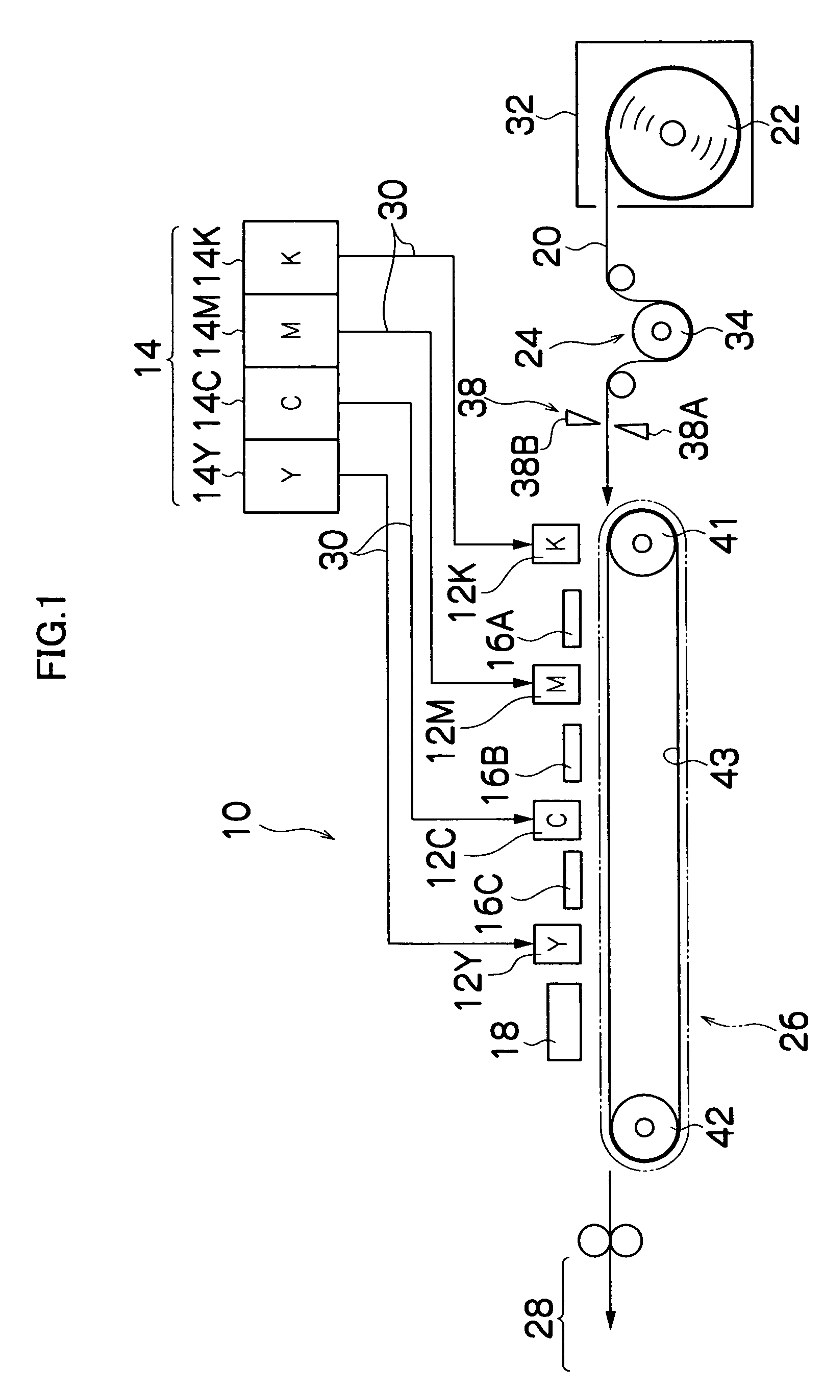
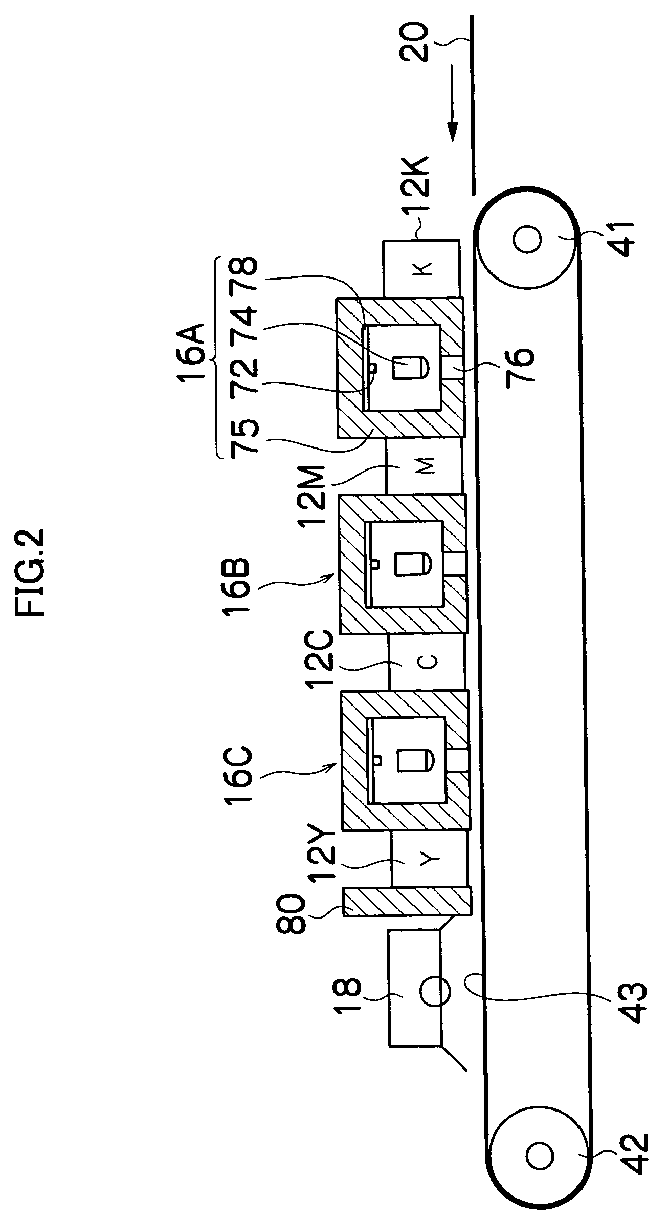
[0117]FIG. 9 is a general compositional diagram of an inkjet recording apparatus according to a fourth embodiment of the present invention. As shown in FIG. 9, this inkjet recording apparatus 110 comprises a print unit 112 having a plurality of print heads 112K, 112C, 112M, 112Y provided corresponding to respective ink colors; an ink storing and loading unit 114 for storing ink to be supplied to the print heads 112K, 112C, 112M and 112Y; a paper supply unit 118 for supplying record paper 116; a decurling unit 120 for removing curl in the record paper 116; a suction belt conveyance unit 122, disposed facing the nozzle face (ink discharge face) of the print unit 112, for conveying the record paper 116 while keeping the record paper 116 flat; a print determination unit 124 for reading in the print results; and a paper output unit 126 for outputting the recorded record paper (printed matter) to the exterior.

[0118]In FIG. 9, a single magazine for rolled paper (continuous paper) is shown ...


PUM


Abstract

An inkjet recording head including first and second supply paths. The first supply path supplies ink to the pressure chamber. The second supply path supplies ink to the porous member. Also included is an orifice plate having the ink discharge port, where at least an inner wall of the ink discharge port is made from the porous member capable of being impregnated with ink. A pressure control device controls pressure of the ink to satisfy the equation P1<P2≦P0, where P1 is the pressure of the ink at a meniscus surface inside the ink discharge port, P2 is the pressure of the ink at a surface of the porous member forming the inner wall of the ink discharge port, and P0 is an atmospheric pressure.

Description

BACKGROUND OF THE INVENTION[0001]1. Field of the Invention[0002]The present invention relates to an inkjet recording head and an inkjet recording apparatus, and in particularly, relates to a maintenance technology for an inkjet recording head, which performs recording by discharging ink from a nozzle onto a recording medium.[0003]2. Description of the Related Art[0004]Inkjet recording apparatuses (inkjet printers) are widely used because the inkjet recording apparatuses are relatively inexpensive, simple to handle, and capable of producing images of high quality. A commonly used inkjet recording apparatus comprises an inkjet recording head (a print head) having a plurality of nozzles, and discharges ink from the nozzles onto a record paper to perform printing. Hence, if the viscosity of the ink increases or the ink hardens due to the evaporation of the solvent or the like, then blocking of the nozzles may occur and it may become difficult to achieve the ink discharge. In the light o...

Claims


Application Information

Patent Timeline
Patent Type & Authority Patents(United States)
IPC IPC(8): B41J2/135B41J2/175B41J29/38B41J2/01
CPCB41J2/165B41J11/002B41J2/16552B41J2002/16502B41J11/00218B41J11/00212B41J11/00214
Inventor KADOMATSU, TETSUZOKONNO, MASAAKI
Owner FUJIFILM CORP
Why Eureka
Try Eureka