Apparatus for removing noxious contaminants from drainage water

a technology for removing noxious contaminants and drainage water, which is applied in the direction of sediment separation, water/sewage treatment by ion exchange, and sedimentation settling tanks, etc. it can solve the problems of water sources contaminated with pernicious slightly soluble organic compounds, benzene, toluene, etc., and achieve strong affinities

Inactive Publication Date: 2002-01-08
MYCELX TECH CORP
View PDF5 Cites 29 Cited by
  • Summary
  • Abstract
  • Description
  • Claims
  • Application Information

AI Technical Summary

Benefits of technology

Now in accordance with the present invention, it has been found that by incorporating certain fluid-previous filtration materials into or at drainage water accessible portions of drainage separating tanks, both oily water insoluble contaminants (e.g. oil spills, asphalt spills and the like), as well as slightly soluble organics such as benzene, toluene, xylene, halogenated hydrocarbons, ethoxylated glycols, etc., may be readily removed from the drainage water, leaving a safe water product for discharge from the separating tank. The filtration materials used incorporate the compositions disclosed in the present inventor's U.S. Pat. Nos. 5,437,793; 5,

Problems solved by technology

Simple rainstorms can generate torrents of water on city streets, and at paved and unpaved parking and other facilities, which water as it sweeps over these surfaces and into drains and catch basins, carries with it large quantities of oils, pernicious chemicals and the like, not to mention various solid and semisolid debris.
Aside from the addition of water insolubles such as oils and greases, this leads to the water sources being contaminated with pernicious slightly soluble organic compounds such as benzene, toluene, xyl

Method used


Image

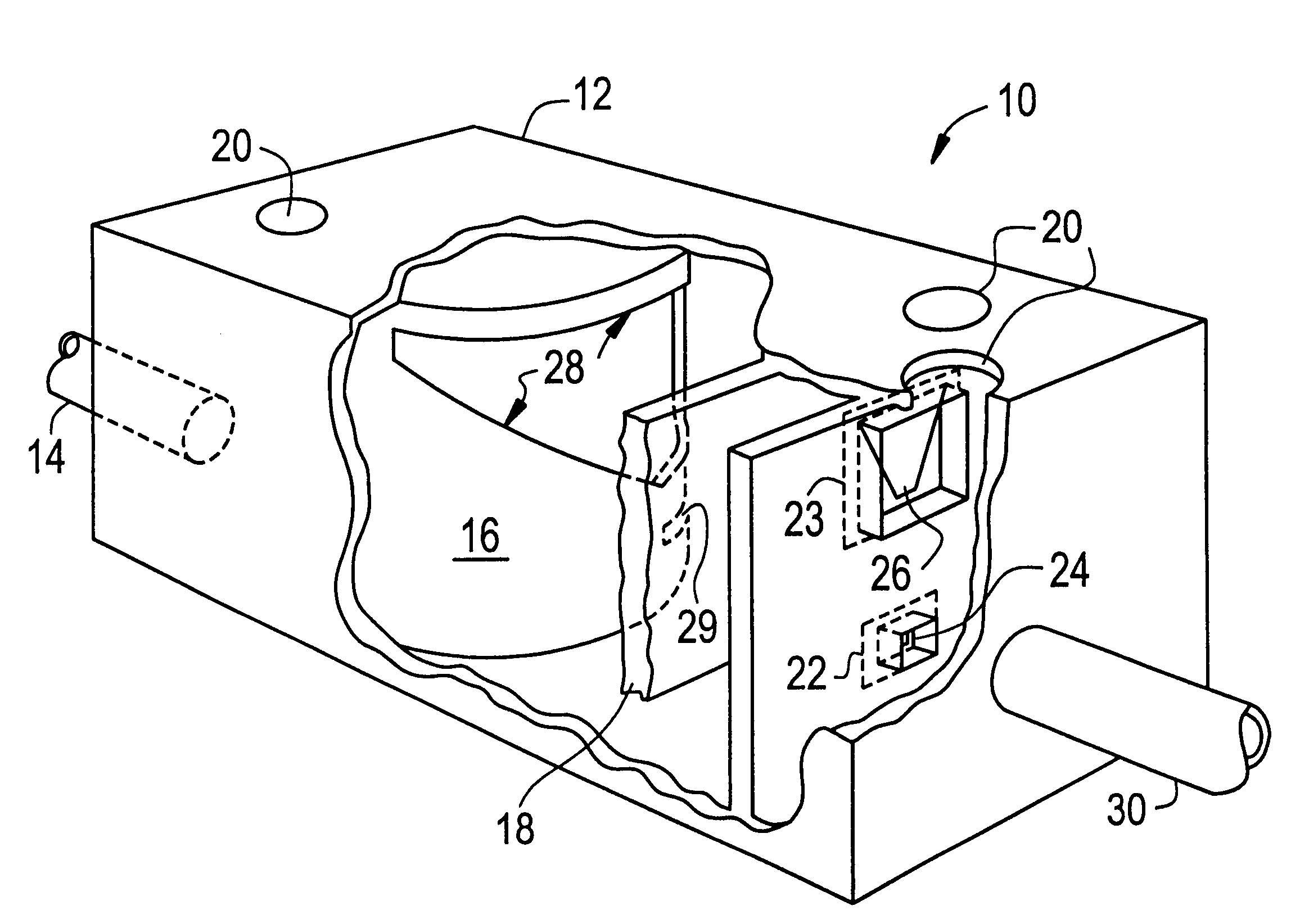
  • Apparatus for removing noxious contaminants from drainage water
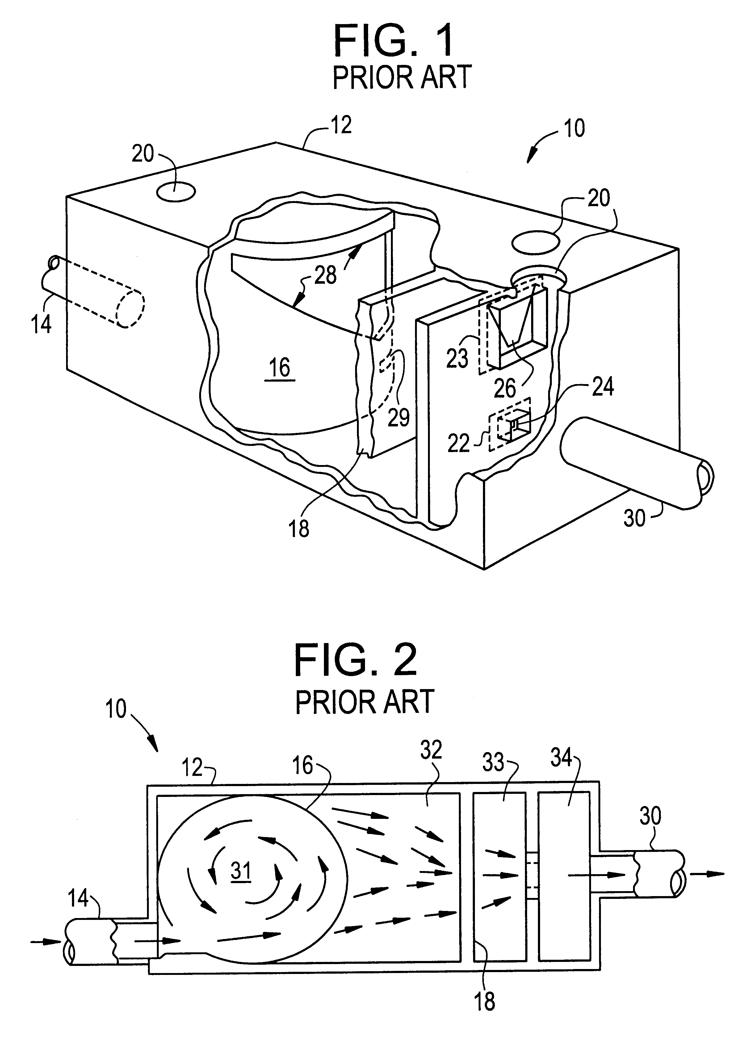
  • Apparatus for removing noxious contaminants from drainage water
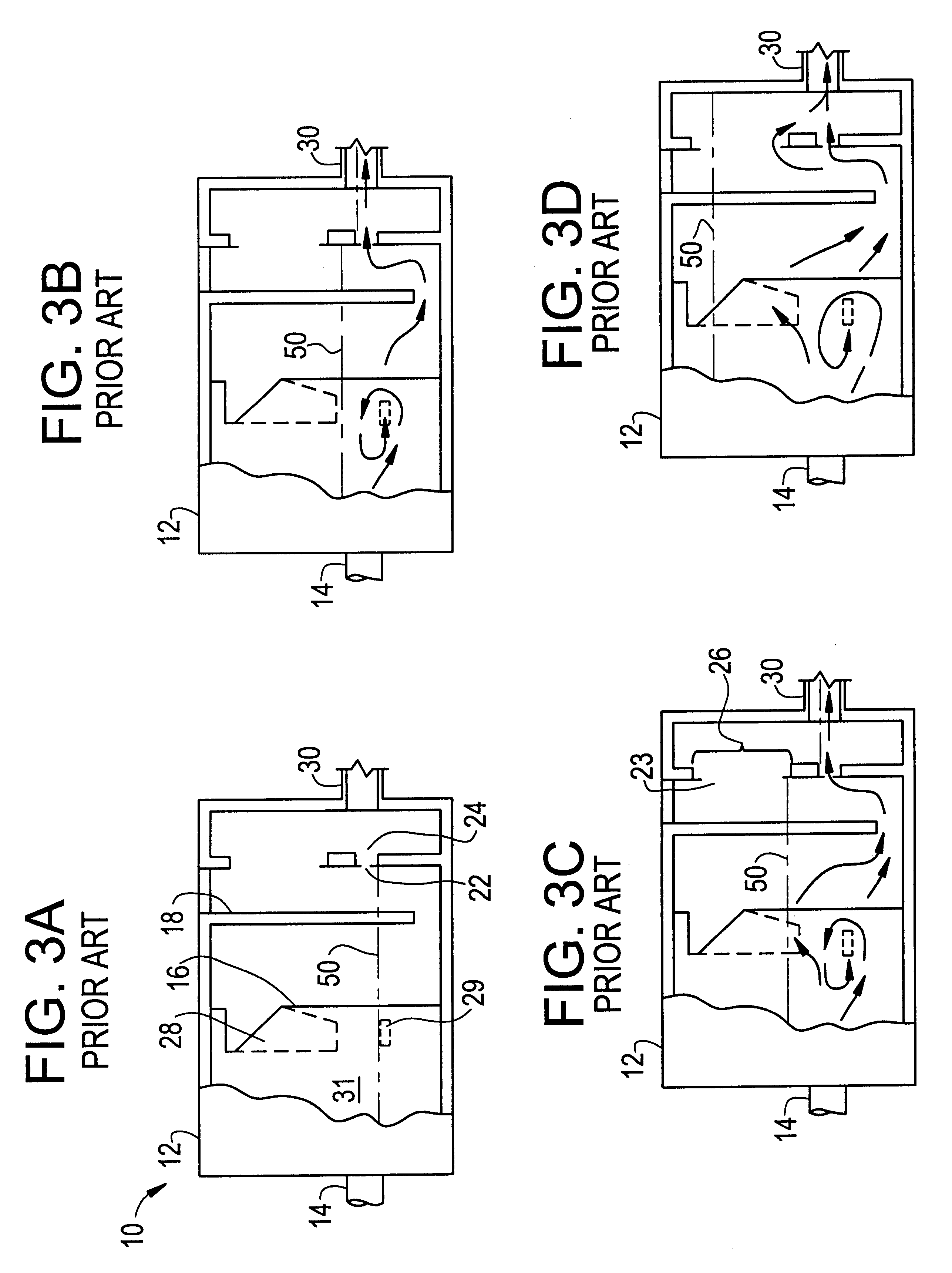
  • Apparatus for removing noxious contaminants from drainage water

Examples


example 1

In order to prepare a filter substrate for use in the invention, an infusion solution is prepared from a suitable solvent and the absorbent composition. In this example a solution was prepared from 90 w / w 99.9% acetone and 10 w / w absorbent composition which is the reaction product of 31% isobutyl methacrylate, 31% ELVACITE 2045, and 66% linseed oil. The absorbent composition is added to a closed explosion-proof mixer with the acetone and mixed for 12 hours or until the solution becomes homogeneous. The substrate in this Example was a nonwoven polypropylene, viz. the VERASPUN material of Yarorough & Co., Inc. of High Point N.C. This material has a weight of 1 oz. / square ft. The substrate material was immersed in the infusion solution until saturated, then removed and excess liquid allowed to drip off. The material was then placed in a convection oven at 110 to 120 deg F. until acetone free. The material was then cured at room temperature for one week. The resulting material was then ...

example 2

Filter Test Results

Effectiveness of the treated filter material of Example 1 is illustrated as a selective oil and organic chemical filter. The identity of these samples and the procedure are as follows:

1d - 5,000 ppm Gasoline 2d - 5,000 ppm Emulsified Diesel Fuel 3d - 20,000 ppm Emulsified Light Crude Oil 4d - 50,000 ppm (50 / 50) Toluene / Xylene

Procedure: 750 g. of deionized water (20 megaohm) spiked with quantity sufficient dopant to achieve desired initial concentrations was passed through a tube of shredded polypropylene(VERASPUN) material 1 (weight=40 g) at a rate of about 0.5 L / minute with approximate contact time of 1.5 sec. The entire 750 ml was processed through the filter material and collected. A 50 ml sample of each effluent was drawn and analyzed using the standard EPA method for total organic carbon.

Conditions: contact time=1.5 sec. Filter wt=40 gm Effluent wt=750 gm

Results Initial Concentration Final Concentration Gasoline 5,000 ppm 93.9 ppm Emulsified Diesel 5,000 ppm ...

example 3

Seven further samples of contaminated water were subjected to the following test. Using the procedure of Example 1, an AMETEK 5 micron polypropylene sediment filter Model P5 (Ametek, Inc., Sheboygan, Wis. 53082) was infused with the absorbent composition and allowed to cure. This filter was subsequently placed in a polypropylene filter cartridge assembled and attached to a centripetal pump with a flow rate of 3 gal / min. One liter solutions of the following contaminated water samples were prepared.

1) 2% Light Crude Oil / H.sub.2 O

2) 0.5% W / W Gasoline / H.sub.2 O

3) 2% Light Crude Oil / H.sub.2 O

4) 100 ppm III Trichloroethane / H.sub.2 O

5) 0.7% Light Crude Oil / H.sub.2 O

6) 100 ppm III Trichloroethane / H.sub.2 O

7) 100 ppm Naptha / H.sub.2 O

Each entire sample was placed in a 3 liter beaker and allowed to circulate through the pump for one minute. At that time, a 100 ml sample was taken from the outflow hose on the pump. The samples after being passed through the filter were subjected to total organi...


PUM

PropertyMeasurementUnit
Flow rateaaaaaaaaaa
Solubility (mass)aaaaaaaaaa

Abstract

The invention relates to an improvement in known apparatus for removing or separating certain contaminants and debris from drainage water. The known device has a tank defining a chamber with an inlet and a pair of vertically spaced outlets. A bulkhead with openings is spaced opposite the inlet and extends from the base of the chamber. A baffle is located between the bulkhead and the outlets and extends from the top of the chamber to near the bottom. An orifice plate or plates is adjustable mounted in series with the outlets and controls the rate of flow therethrough. The system thus has four sections, namely a non-floating particulate containment chamber; a floating particulate containment chamber; a flow control chamber; and an outlet chamber. In accordance with the invention, a fluid-previous media is provided at the interior of said apparatus in or abounding the flow path of the drain water proceeding between said inlet and outlet. The media is infused with a composition comprising a homogeneous thermal reaction product of an oil component selected from the group consisting of glycerides, fatty acids, alkenes, and alkynes, with a methacrylate or acrylate polymer component; the said contaminants in the drain water flowing through said apparatus thereby coming into intimate contact with and being immobilized at said media.

Description

This invention relates generally to apparatus for removing noxious contaminants from aqueous systems, and more specifically relates to filtration devices and methods for removing both oily and slightly soluble organic compounds from such aqueous systems. The invention is particularly applicable to the removal of such contaminants from drainage water, such as collected rainwater.BACKGROUND OF INVENTIONIncreasing public awareness and concern regarding the effects on human and animal life of contamination of water sources, has led in recent years to the focusing of attention on contamination of drainage water. Simple rainstorms can generate torrents of water on city streets, and at paved and unpaved parking and other facilities, which water as it sweeps over these surfaces and into drains and catch basins, carries with it large quantities of oils, pernicious chemicals and the like, not to mention various solid and semisolid debris. A graphic picture of such events can be visualized by ...

Claims


Application Information

Patent Timeline
IPC IPC(8): B01D15/00
CPCB01D21/0012B01D21/003B01D21/2411B01D17/0202C02F1/40C02F1/288B01D2221/12E03F5/14C02F1/285C02F2101/32C02F2101/322C02F2101/36C02F2103/001C02F1/24
Inventor ALPER, HALUK
Owner MYCELX TECH CORP
Why Eureka
Try Eureka