Exhaust unit, exhausting method, and semiconductor manufacturing facility with the exhaust unit

Inactive Publication Date: 2008-07-03
SAMSUNG ELECTRONICS CO LTD
View PDF0 Cites 8 Cited by
  • Summary
  • Abstract
  • Description
  • Claims
  • Application Information

AI Technical Summary

Benefits of technology

[0007]The present invention provides an exhaust unit and exhausting method capable of efficiently control

Problems solved by technology

However, when pressure variation over a wide range occurs during use of typical exhaust units as those described above, the pressure within the process chamber also fluctuates over a wide range, leading to manufacturing

Method used


Image

  • Exhaust unit, exhausting method, and semiconductor manufacturing facility with the exhaust unit
  • Exhaust unit, exhausting method, and semiconductor manufacturing facility with the exhaust unit
  • Exhaust unit, exhausting method, and semiconductor manufacturing facility with the exhaust unit

Examples


Example

[0040]Preferred embodiments of the present invention will be described below in more detail with reference to FIGS. 2 through 17. The present invention may, however, be embodied in different forms and should not be constructed as limited to the embodiments set forth herein. Rather, these embodiments are provided so that this disclosure will be thorough and complete, and will fully convey the scope of the present invention to those skilled in the art. Thus, elements in the drawings are exaggerated for clarity of illustration.

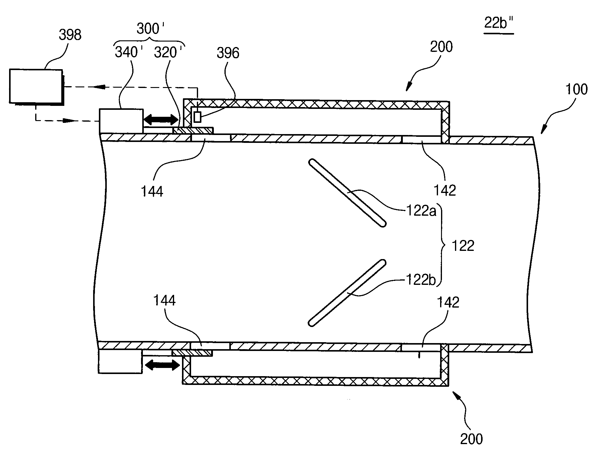
[0041]Hereinafter, an exemplary embodiment of a structure of an exhaust unit 20 provided on a semiconductor manufacturing facility 1 according to the present invention will be described. The technical scope of the present invention, however, is not limited hereto, and the exhaust unit 20 may be employed in various other applications in which exhaust volume fluctuates due to external influences.

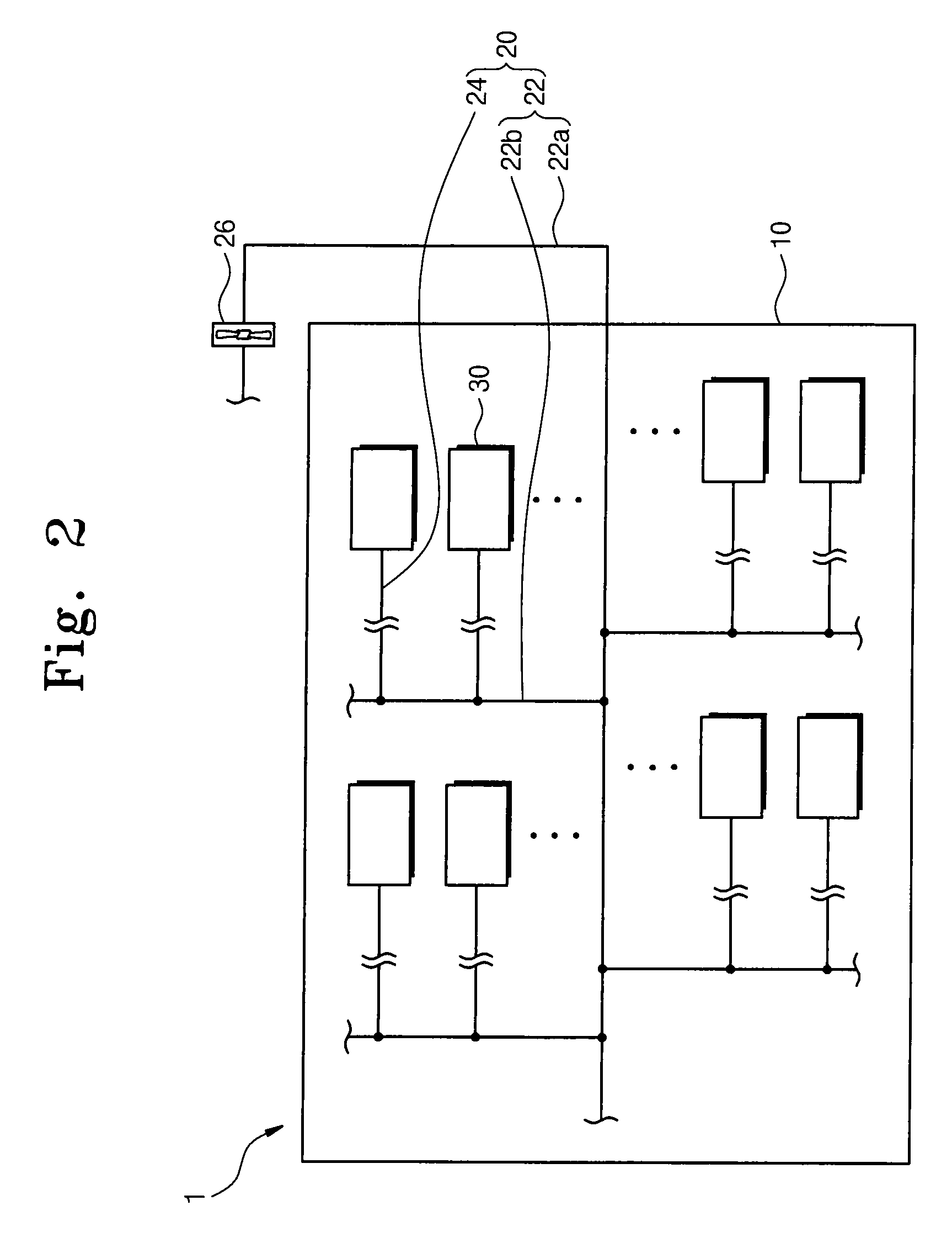
[0042]FIG. 2 is a plan view of a semiconductor manufacturing facility ...


PUM


Abstract

Provided is an exhaust unit capable of preventing large pressure fluctuations within a process chamber due to atmospheric pressure changes. The exhaust unit includes a main exhaust duct and a supplemental exhaust duct that acts as a partial bypass. A flap is located at a downstream opening between the main exhaust duct and supplemental exhaust duct and controls the amount of bypassed gas flowing from the supplemental exhaust duct to the main exhaust duct. First and second plates of the flap are pivotally coupled to the main exhaust duct adjacent the downstream opening, the first plate colliding with gas flowing through the main exhaust duct and the second plate partially blocking bypassed gas flowing back into the main exhaust duct from the supplemental exhaust duct. When gas is exhausted through the main exhaust line and the supplemental exhaust duct, the flap passively controls the amount by which the supplemental exhaust duct is opened through fluctuations in atmospheric pressure.

Description

CROSS-REFERENCE TO RELATED APPLICATIONS[0001]This U.S. non-provisional patent application claims priority under 35 U.S.C. §119 of Korean Patent Application No. 10-2007-00740, filed on Jan. 3, 2007, the entire contents of which are hereby incorporated by reference.BACKGROUND OF THE INVENTION[0002]The present invention disclosed herein relates to a semiconductor manufacturing facility, and more particularly, to an exhaust unit and an exhausting method for exhausting gas from a process chamber to lower the pressure within the process chamber.[0003]Typically, a semiconductor manufacturing facility has a plurality of process chambers within a clean room and exhaust units that control the pressures within the process chambers. Each process chamber is connected to a branch duct for exhausting gas from therein, and the respective branch ducts are connected to a main duct. The main duct is formed of a primary duct with a fan installed, and a secondary duct connected to the branch ducts. Typi...

Claims


Application Information

Patent Timeline
IPC IPC(8): F24F7/00H01L21/02F24F13/10
CPCF24F2011/0042F24F11/022F24F2110/40F24F11/72F24F2140/10H01L21/02
Inventor KIM, MOON-JEONGAHN, KANG-HOKANG, SUCK-HOONLEE, JAE-YOUNGCHOI, JAI-HEUNGHWANG, JUNG-SUNG
Owner SAMSUNG ELECTRONICS CO LTD
Why Eureka
Try Eureka