
Self-guided portable medical diagnostic system

a portable, medical technology, applied in the field of medical diagnostic systems, can solve the problems of cumbersomeness, waste of manpower in operating the devices, and a lot of manual effort in physically moving the portable devices around the hospital

Active Publication Date: 2008-07-03
GENERAL ELECTRIC CO
View PDF25 Cites 49 Cited by
  • Summary
  • Abstract
  • Description
  • Claims
  • Application Information

AI Technical Summary

Benefits of technology

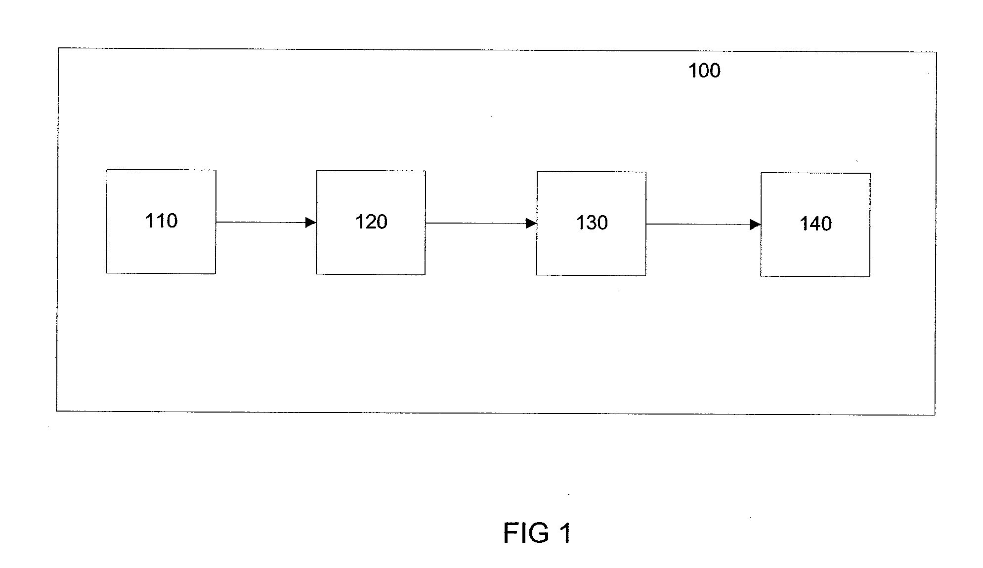
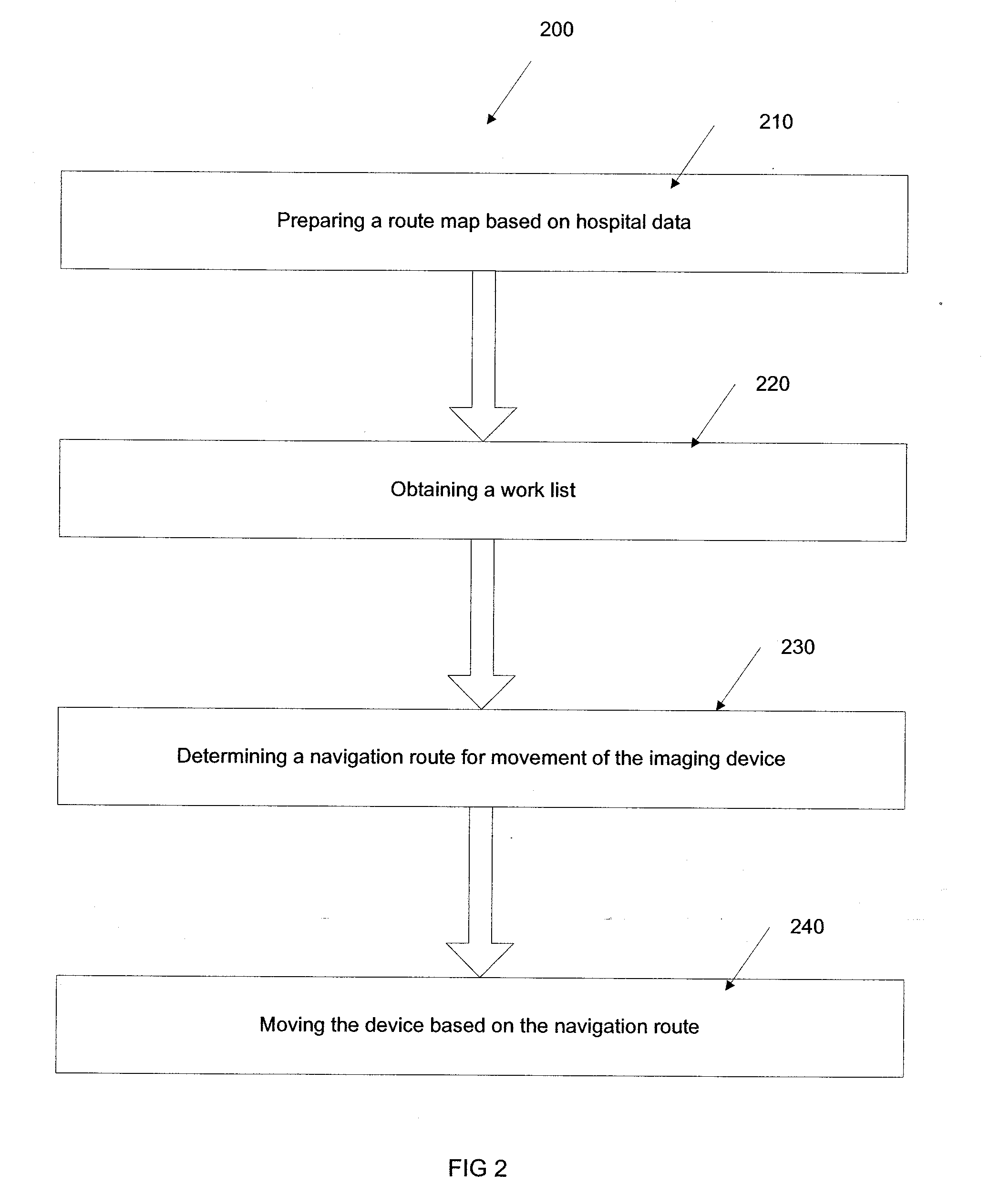
"The present invention provides a medical diagnostic device with an automatic moving mechanism. This device can be a medical imaging device or a patient monitoring device. The device has an input interface for receiving instructions, a motion controller for controlling movements, and a moving assembly for moving the device under control of the motion controller. The device can also be guided to specific locations in a hospital using a route map and a work list. The self-guided portable medical imaging system includes a medical imaging device and a robotic controller with a processor and a moving assembly for guiding the movement of the device. The technical effects of this invention include improved efficiency, accuracy, and convenience in medical diagnosis and monitoring."

Problems solved by technology

There involves many problems in manually operating the portable device.
One of the significant problems is wastage of manpower in operating the devices.
Also it requires a lot of manual effort in physically moving the portable devices all around the hospital.
This will become cumbersome if there is a need for retake especially in the case of equipment failure.
Another problem existing in the field is in deciding an optimal route for the movement of the device.
So many times the operator will not be able to decide an optimal route manually.
This will lead to wastage of time and inefficient use of the device.
This problem will became more significant in the case of bigger hospitals where there are different floors and increased numbers of patients to be scanned.

Method used


Image

  • Self-guided portable medical diagnostic system
  • Self-guided portable medical diagnostic system
  • Self-guided portable medical diagnostic system

Examples


Embodiment Construction

[0016]In the following detailed description, reference is made to the accompanying drawings that form a part hereof, and in which is shown by way of illustration specific embodiments that may be practiced. These embodiments are described in sufficient detail to enable those skilled in the art to practice the embodiments, and it is to be understood that other embodiments may be utilized and that logical, mechanical, electrical and other changes may be made without departing from the scope of the embodiments. The following detailed description is, therefore, not to be taken as limiting the scope of the invention.

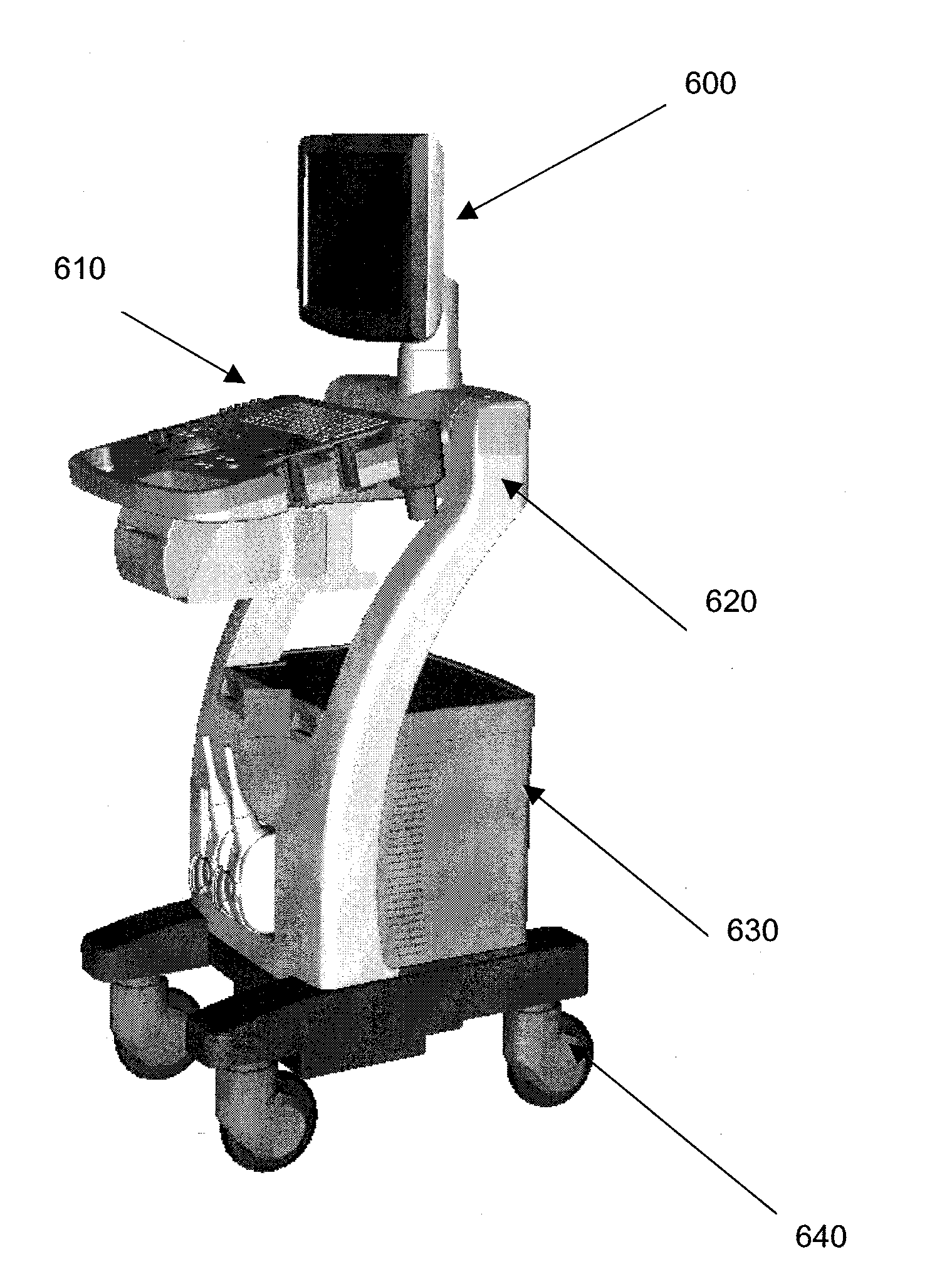
[0017]In various embodiments, an imaging system with an automatic moving mechanism is described. A portable imaging or diagnostic device with an automatic moving mechanism for moving the device without any manual effort of an operator is disclosed. In an embodiment, the automatic moving mechanism associated with the imaging device is configured to accept commands from an exter...


PUM


Abstract

The present invention provides a medical diagnostic device with an automatic moving mechanism. The device comprises an input interface for receiving instructions from an operator or from a remote device. A motion controller is coupled to the input interface for controlling movements of the diagnostic device based on the instructions received through the input interface. A moving assembly is coupled to the motion controller for moving the diagnostic device under control of the motion controller. In an embodiment, a method of guiding a portable imaging system through various locations in a hospital is disclosed. Also the invention discloses a self-guided portable imaging system.

Description

FIELD OF THE INVENTION[0001]This invention generally relates to a medical diagnostic system and more particularly to a portable medical diagnostic system with an automatic moving mechanism.BACKGROUND OF THE INVENTION[0002]In the current diagnostic and medical imaging technology, many portable diagnostic or imaging devices are used. However the portable medical imaging or diagnostic devices today rely on the operator pushing the device within the hospital, sometimes with the help of power assisted devices. The operator has to move the device from its parking place to various patient locations using manual force. This could include typically moving the equipment across different floor locations as well as different areas of the hospital. There involves many problems in manually operating the portable device. One of the significant problems is wastage of manpower in operating the devices. Also it requires a lot of manual effort in physically moving the portable devices all around the h...

Claims


Application Information

Patent Timeline
Patent Type & Authority Applications(United States)
IPC IPC(8): A61B5/05
CPCA61B5/055A61B6/4405Y10S901/01A61B8/4405A61B2560/0431A61B8/00A61B5/7475
Inventor MARAR, RAJEEV RAMANKUTTY
Owner GENERAL ELECTRIC CO
Learn More