Surface charge measuring system with external motion control mechanism and measuring method
A surface charge and motion control technology, applied in the direction of measuring electrical variables, measuring devices, instruments, etc., can solve the problems of difficult measurement of surface charge, achieve the effects of reducing SF6 amount, increasing safety distance, and high spatial resolution
- Summary
- Abstract
- Description
- Claims
- Application Information
AI Technical Summary
Problems solved by technology
Method used
Image
Examples
Embodiment 1
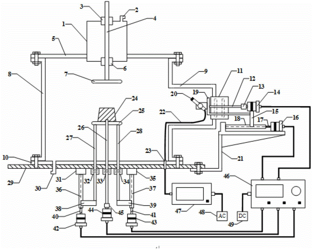
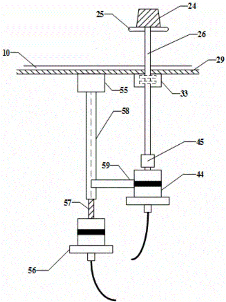
[0045] This embodiment discloses a surface charge measurement system with an external motion control mechanism, which is characterized in that it mainly includes a main casing 8, a side casing 9, an upper parallel plate electrode 7, a lower parallel plate electrode 25, and an electrostatic measurement probe 20 And high-speed high-voltage electrostatic potentiometer 47.
[0046] The main casing 8 is a hollow cylinder with open upper and lower ends, and has a hollow inner chamber. The lateral housing 9 is a hollow cylinder with one end open and the other closed, which also has a hollow inner chamber.
[0047] The axial direction of the main housing 8 is perpendicular to the horizontal plane, and the axial direction of the lateral housing 9 is parallel to the horizontal plane. The open end of the side housing 9 is connected to the cylinder wall of the main housing 8 . The cylinder wall of the main housing 8 is provided with a through hole, and the open end of the lateral housin...
Embodiment 2
[0060] The main structure of this embodiment is the same as that of Embodiment 1. Further, the upper end of the high voltage bushing 1 is located above the upper cover plate 5 , that is, the upper end of the high voltage bushing 1 is exposed above the upper cover plate 5 . The lower end of the high voltage bushing 1 protrudes into the inner cavity of the main casing 8 . The high voltage bushing 1 has a hollow inner cavity, and its axial direction is perpendicular to the horizontal plane.
[0061] The upper and lower ends of the high-voltage bushing 1 are provided with through holes for the high-voltage conductive rod 4 to pass through. The first static sealing seat ring 3 and the second static sealing seat ring 6 are respectively embedded in the through holes at the upper and lower ends of the high voltage bushing 1 . The lower end of the high-voltage conductive rod 4 first passes through the first static sealing seat 3 and then the second static sealing seat 6, and then ext...
Embodiment 3
[0063] The main structure of this embodiment is the same as that of Embodiment 1.
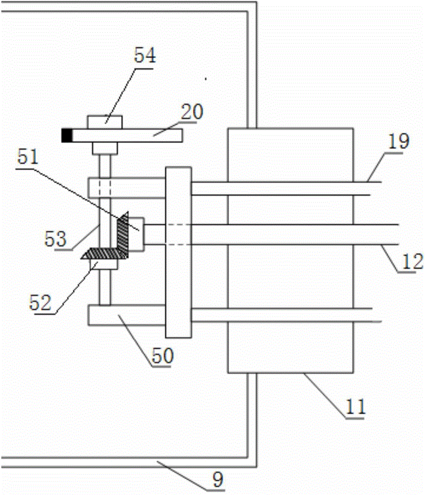
[0064] Further, it also includes a rotating shaft fixing bracket 50 located in the inner cavity of the lateral housing 9 . The first dynamic seal seat ring 11, the transverse rotation shaft 12, the first reducer 13, the first stepper motor 14, the second stepper motor 16, the transverse slider 15, the transverse guide rail 18, the transverse ball screw 17, the drive Bevel gear 51, driven bevel gear 52, probe frame 54, gear rotating shaft 53, rotating shaft fixing frame 50, transverse polished rod 19 and bottom bracket 21 etc. form the mechanism for controlling the movement of the measuring probe.
[0065] The second stepper motor 16 drives the horizontal slider 15 to move in the horizontal direction. The transverse slider 15 is connected to one end of a transverse polished rod 19 . The other end of the transverse polished rod 19 is inserted into the lateral casing 9 and connected with the rot...
PUM
 Abstract
Description
Claims
Application Information
 - R&D
- Intellectual Property
- Life Sciences
- Materials
- Tech Scout
- Unparalleled Data Quality
- Higher Quality Content
- 60% Fewer Hallucinations
Browse by: Latest US Patents, China's latest patents, Technical Efficacy Thesaurus, Application Domain, Technology Topic, Popular Technical Reports.
© 2025 PatSnap. All rights reserved.Legal|Privacy policy|Modern Slavery Act Transparency Statement|Sitemap|About US| Contact US: help@patsnap.com


