
Airtight tester

a tester and airtight technology, applied in the direction of measuring devices, instruments, structural/machine measurement, etc., can solve the problems of not knowing the circumstances, unable to conduct further research and development for improving the products based on the information of the testing process, and cannot achieve the effect of conventional testing tables, etc., to achieve the effect of easy operation and high operating flexibility in application

Inactive Publication Date: 2008-07-10
SMARTANT TELECOMM
View PDF22 Cites 18 Cited by
  • Summary
  • Abstract
  • Description
  • Claims
  • Application Information

AI Technical Summary

Benefits of technology

[0011]The present invention of the airtight tester, the testing staff directly observes the bearing capability of the object to be tested during the overall airtight testing process, which is convenient for the testing staff to analyze or adjust the testing status. As compared with the conventional art that the test result can only be known indirectly, the present invention enables the testing staff to master the whole testing process according to the test requirements, and meanwhile to obtain more direct and detailed test information. In addition, the leakage-test pipe adopts a hand-held design. As for the testing staff, if it intends to test a single part of the object to be tested, the testing position of the object to be tested may be selected, and meanwhile the leakage-test pipe directly covers thereon, for example, the position where the pins and the main body of the object to be tested are jointed together, so as to perform the airtight test. Therefore, the testing staff can change the position covered by the leakage-test pipe according to the testing requirements, and thus, the present invention has a higher operating flexibility in application and can be easily operated.

Problems solved by technology

With the above conventional art, the manufacturer cannot know the circumstances generated to the products during the testing process, so it cannot conduct further research and development for improving the products based upon the information of the testing process.
In addition, the conventional art aims at testing the leakage-proof function of the whole object to be tested, if it intends to test a single part of the object to be tested, it cannot be achieved through the conventional testing table.

Method used


Image

  • Airtight tester
  • Airtight tester
  • Airtight tester

Examples


Embodiment Construction

[0018]In order to make the objective, structure, feature, and function of the present invention be more comprehensible, a detailed description is given below through embodiments.

[0019]The present invention of the airtight tester is used to test the air tightness of an object to be tested. The object is, but not limited to, an outdoor antenna, a PDA, a GPS navigator, a cell phone, or other electronic products. For example, products meeting dustproof and waterproof performance level IP67 may also apply the technique provided by the present invention. In the embodiments of the present invention, the outdoor antenna is taken as an application embodiment of the object to be tested.

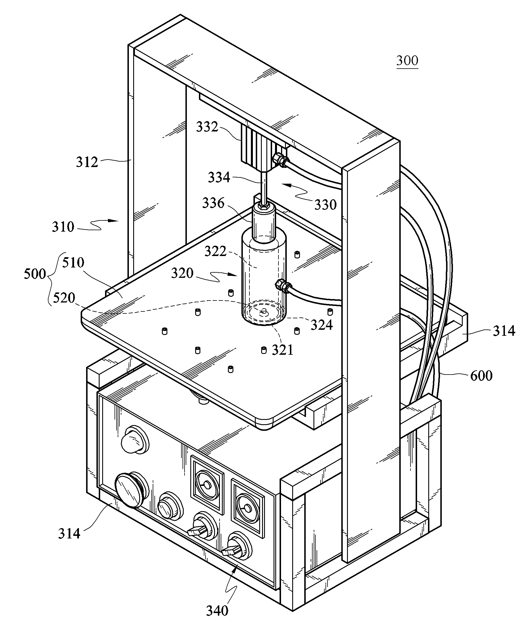
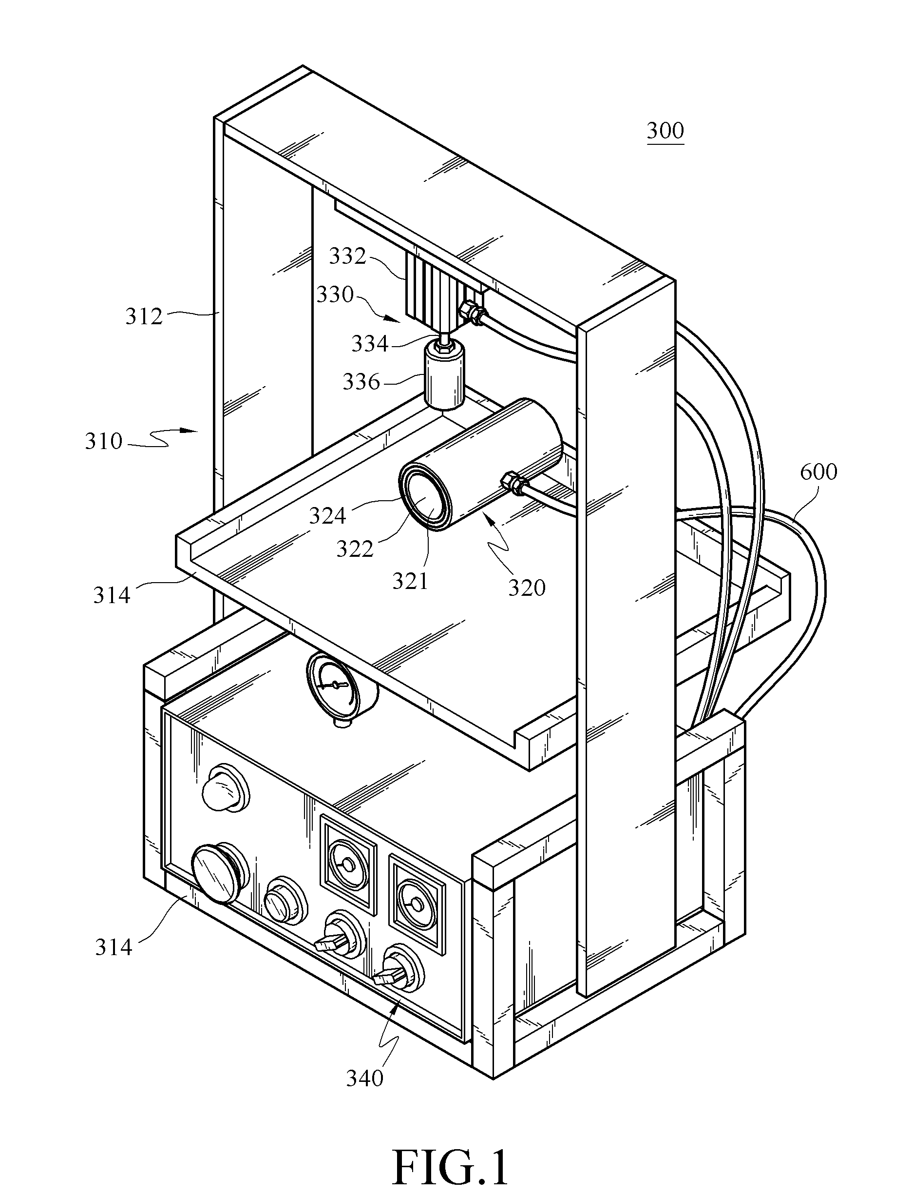
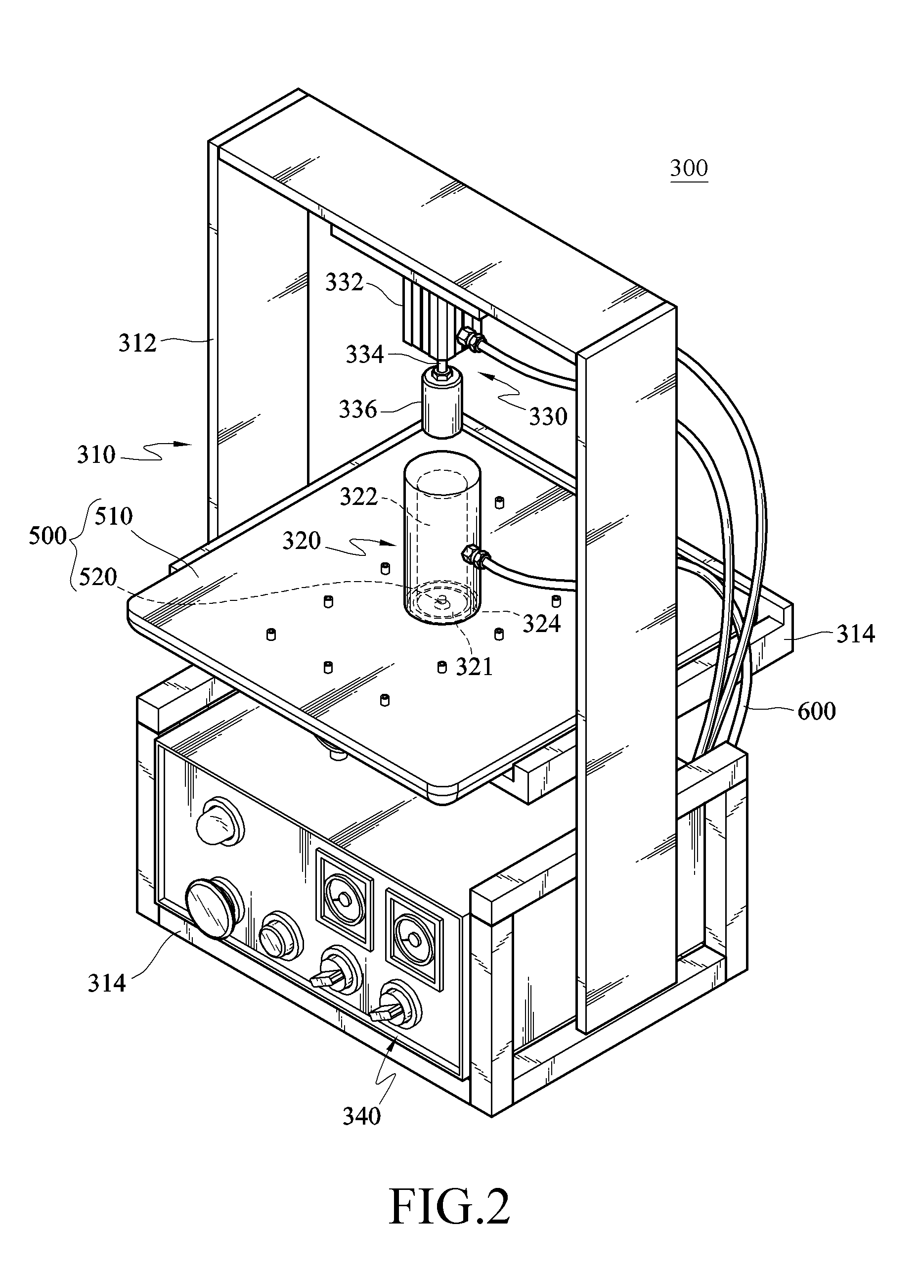
[0020]Referring to FIGS. 1, 2, and 4, an airtight tester 300 is manufactured according to the IP67 Code, but may also be manufactured according to a specification required by the customer. Here, the airtight tester 300 manufactured according to the IP67 Code is taken as an application embodiment herein. An outd...


PUM


Abstract

An airtight tester is used to test air tightness at a testing position of an object to be tested. The airtight tester includes a base, a leakage-test pipe, a moving unit, and a detector. The leakage-test pipe is connected to a pressure source, such that the pressure source may output a pressure to the leakage-test pipe. When the leakage-test pipe covers at the testing position of the object, the moving unit is pressed at an outer edge of the leakage-test pipe, so that the leakage-test pipe is jointed to a surface of the object, and thus, the detector detects the pressure state of the leakage-test pipe. Therefore, the testing staff obtains the air tightness of the object through an output message of the detector, and thus strengthening the structure of the object through utilizing the information.

Description

CROSS-REFERENCE TO RELATED APPLICATIONS[0001]This non-provisional application claims priority under 35 U.S.C. § 119(a) on Patent Application No(s). 096200269 filed in Taiwan, R.O.C. on Jan. 5, 2007, the entire contents of which are hereby incorporated by reference.BACKGROUND OF THE INVENTION[0002]1. Field of the Invention[0003]The present invention relates to an airtight tester. More particularly, the present invention relates to an airtight tester capable of performing airtight test on a single part of an object to be tested.[0004]2. Related Art[0005]Electronic products, for example, personal digital assistances (PDAs), GPS navigators, cell phones, and outdoor antennas are generally used by users under awful natural environment or unstable outdoor environment. Under such environments, dusts and moistures usually may cause damage to the electronic products. Therefore, the electronic products must correspondingly have good dustproof and waterproof effects, such that when the electron...

Claims


Application Information

Patent Timeline
IPC IPC(8): G01M3/04
CPCG01M3/2869
Inventor HSU, YOMAN
Owner SMARTANT TELECOMM
Learn More