Thermoelectric conversion module and thermoelectric conversion apparatus

a technology of thermoelectric conversion module and thermoelectric conversion apparatus, which is applied in the direction of lighting and heating apparatus, machines using electric/magnetic effects, refrigerating machines, etc., can solve the problems of global warming, insufficient efficiency of thermoelectric conversion system for small or medium amount of waste heat generated from small and medium plants, and extremely low power generation efficiency, etc., to achieve superior cost and space, and high power generation per installation area

Inactive Publication Date: 2008-07-10
KK TOSHIBA
View PDF6 Cites 69 Cited by
  • Summary
  • Abstract
  • Description
  • Claims
  • Application Information

AI Technical Summary

Benefits of technology

[0024]The present invention has been made in light of the above situation, and accordingly it is an object of the present invention to provide a thermoelectric conversion module superior in cost and space and exhibiting a high po

Problems solved by technology

As the consumption of energy is rapidly mounting, the emission of greenhouse gases, such as CO2, increases and causes global warming.
However, the efficiency of thermoelectric conversion systems for a small or medium amount of waste heat generated from small and medium plants has not reached a sufficient level in practice.
The use of a steam turbine electric power plant or the like for a small amount of waste heat leads to a

Method used


Image

  • Thermoelectric conversion module and thermoelectric conversion apparatus
  • Thermoelectric conversion module and thermoelectric conversion apparatus
  • Thermoelectric conversion module and thermoelectric conversion apparatus

Examples


first embodiment

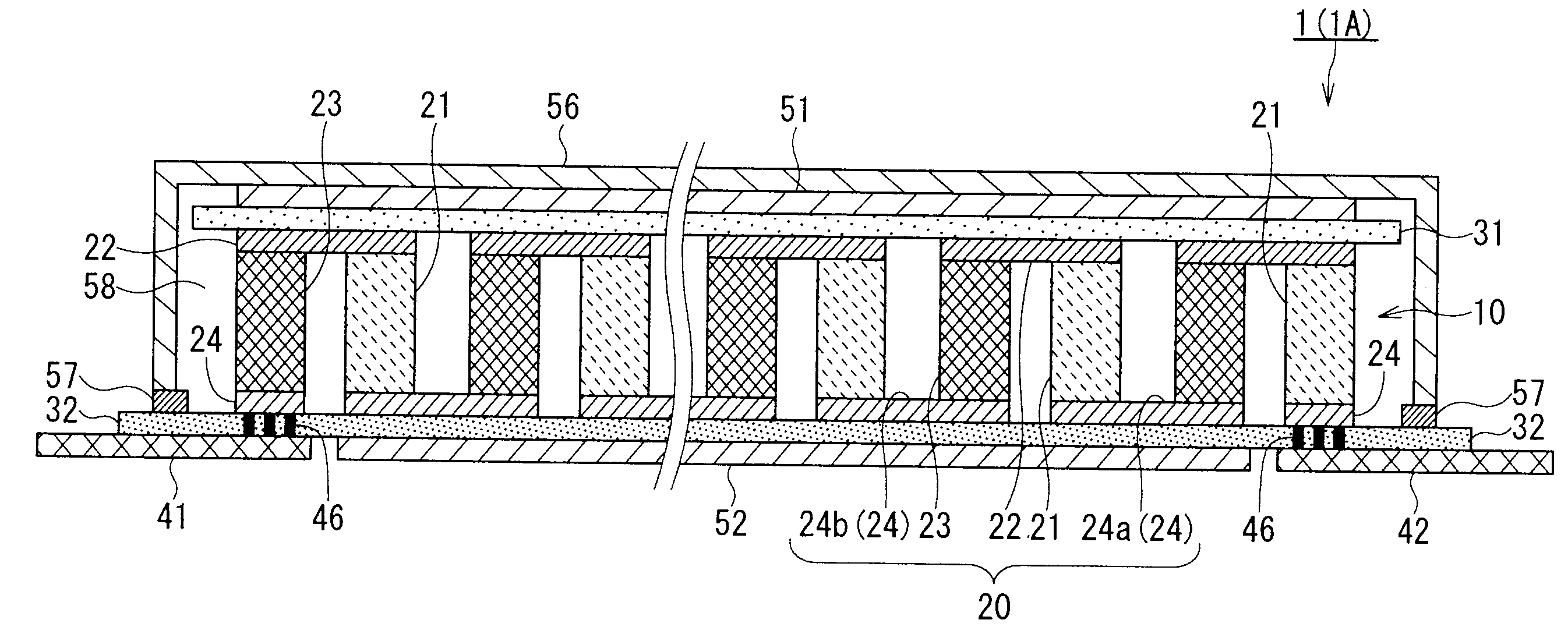
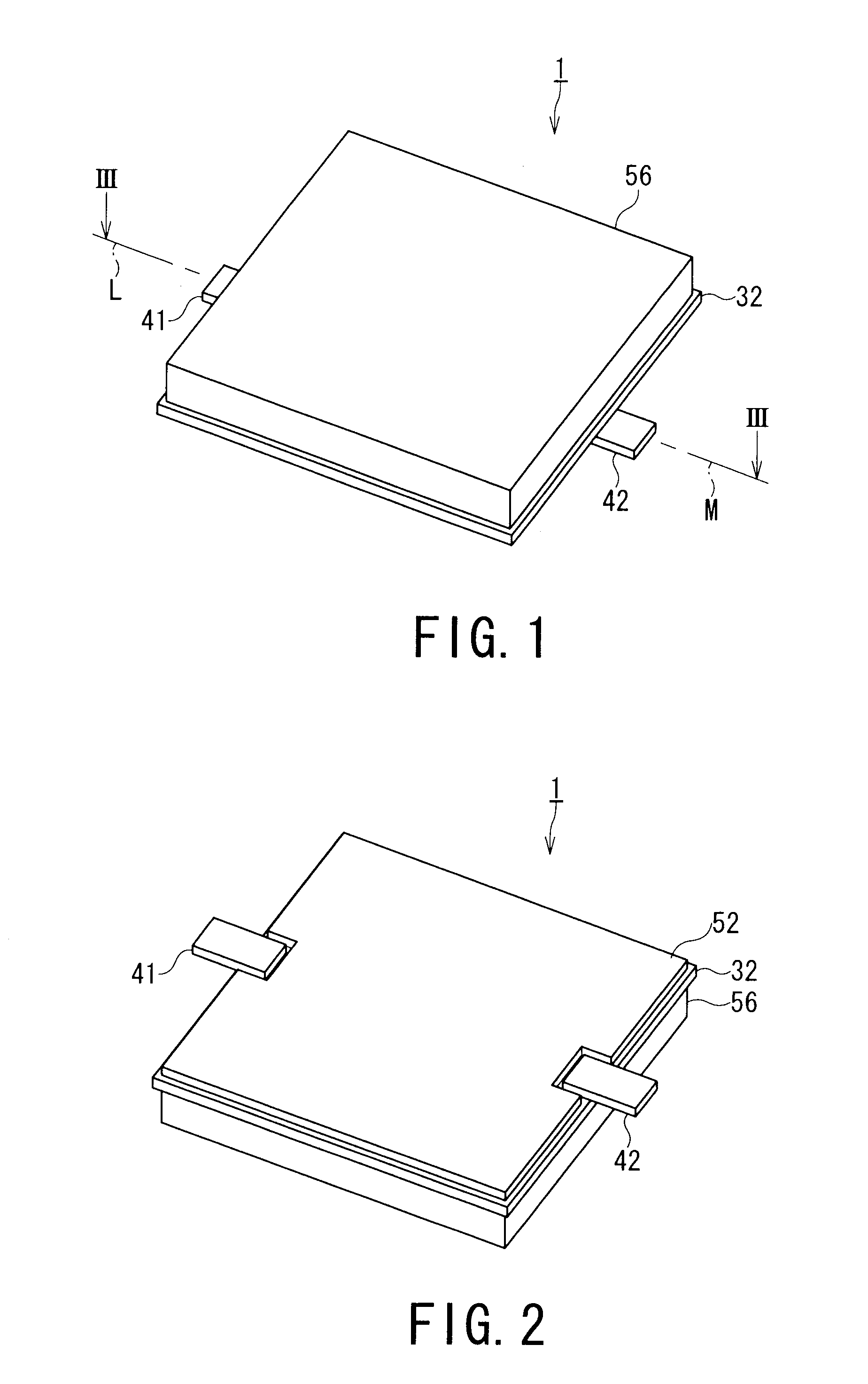
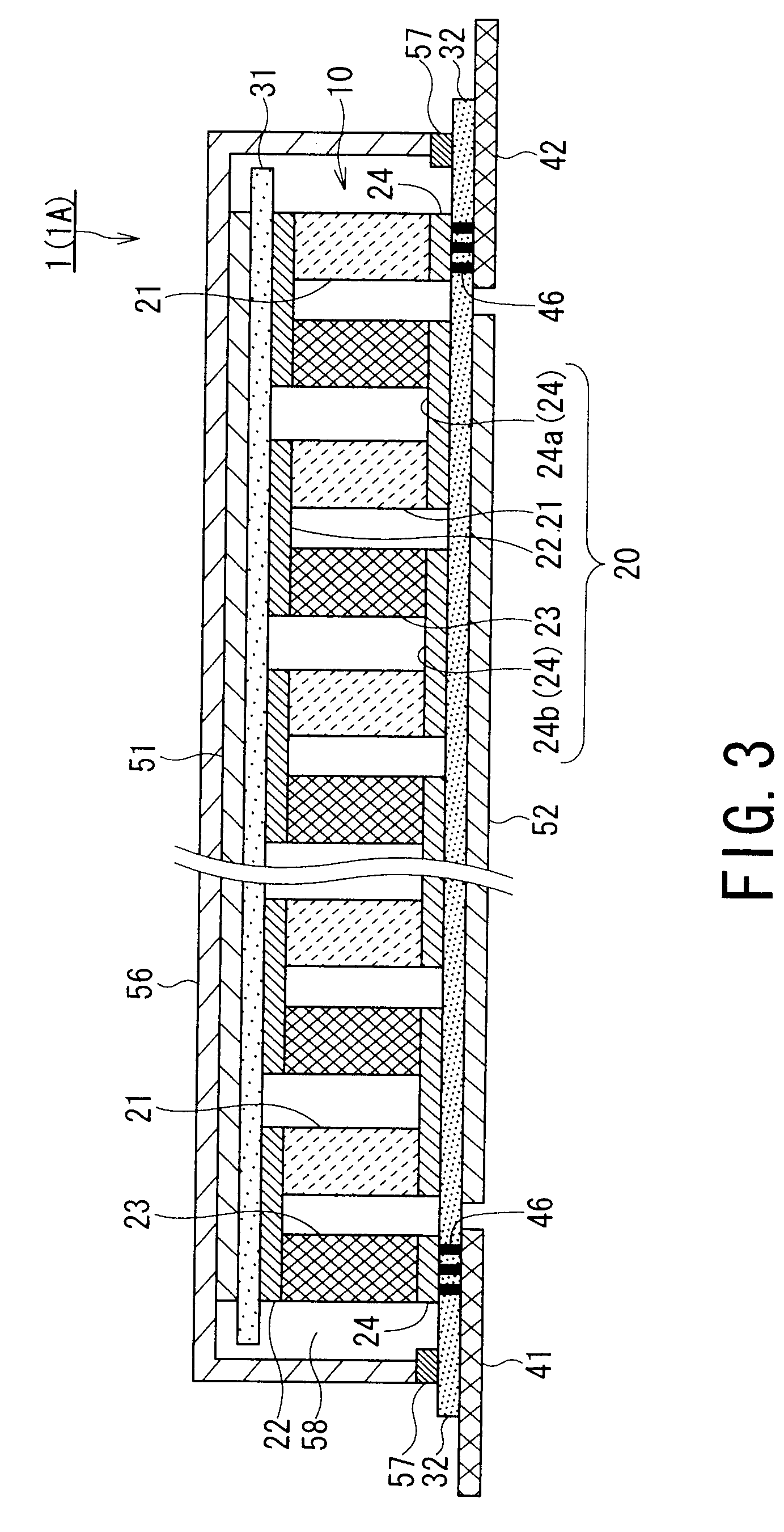
[0044]FIG. 1 is a perspective view of a thermoelectric conversion module 1 according to a first embodiment of the present invention. FIG. 2 is a perspective view of the thermoelectric conversion module 1 shown in FIG. 1 when viewed from the rear side. FIG. 3 is a sectional view of the thermoelectric conversion module 1 taken along line III-III of FIG. 1.

[0045]As shown in FIG. 1 and FIG. 2, the thermoelectric conversion module 1 includes a low temperature insulating layer 32, a casing 56 defining an enclosed housing space 58 in cooperation with the low temperature insulating layer 32, a first external electrode 41, and a second external electrode 42. A thermoelectric conversion portion 10 is housed in the housing space 58 defined by the low temperature insulating layer 32 and the casing 56.

[0046]As shown in FIG. 3, the thermoelectric conversion portion 10 includes low temperature electrodes 24 and a set of n-type thermoelectric conversion semiconductor layer 21 and p-type thermoelect...

second embodiment

[0102]A thermoelectric conversion module according to a second embodiment of the present invention will now be described with reference to FIGS. 8 and 9.

[0103]The thermoelectric conversion module 1A according to the second embodiment has the same structure as the thermoelectric conversion module 1 of the first embodiment, except that a first external electrode 41A and a second external electrode 42A are used instead of the first external electrode 41 and the second external electrode 42. The same parts in the drawings are designated by the same reference numerals, and the descriptions of the same parts will be simplified or omitted.

[0104]FIG. 8 is a plan view of the thermoelectric conversion module 1A according to the second embodiment of the present invention, and FIG. 9 is a bottom view of the thermoelectric conversion module 1A.

[0105]The first external electrode 41A and second external electrode 42A of the thermoelectric conversion module 1A are disposed with the thermoelectric c...

third embodiment

[0111]A thermoelectric conversion module according to a third embodiment of the present invention will now be described with reference to FIG. 10.

[0112]The thermoelectric conversion module 1B of the third embodiment has the same structure as the thermoelectric conversion module 1 of the first embodiment, except that a first external electrode 41B and a second external electrode 2B are used instead of the first external electrode 41 and the second external electrode 42. The same parts in the figure are designated by the same reference numerals, and the descriptions of the same parts will be simplified or omitted.

[0113]FIG. 10 is a perspective view of the thermoelectric conversion module 1B according to the third embodiment of the present invention.

[0114]The first external electrode 41B and second external electrode 42B of the thermoelectric conversion module 1B are made of the same electroconductive metal plate as the first external electrode 41 and second external electrode 42 of th...


PUM


Abstract

According to one embodiment, a thermoelectric conversion module includes a thermoelectric conversion portion, a first external electrode, and a second external electrode. The thermoelectric conversion portion includes a single thermoelectric conversion portion element, or electrically connected thermoelectric conversion portion elements. The thermoelectric conversion portion element includes a high temperature electrode, low temperature electrodes, and an n-type and a p-type thermoelectric conversion semiconductor layer disposed between the high temperature electrode and the low temperature electrodes. The first and the second external electrode are electrically connected to one of the low temperature electrode and another one of the low temperature electrode respectively. The first external electrode and the second external electrode are disposed opposite each other with the thermoelectric conversion portion therebetween in such a manner that the centerlines of the first and second external electrodes are aligned substantially in line with each other.

Description

CROSS-REFERENCE TO RELATED APPLICATIONS[0001]This application claims the benefit of priority of Japanese Patent Application No. 2006-290191, filed Oct. 25, 2006, the entire contents of which are incorporated herein by reference.BACKGROUND[0002]1. Field[0003]The present invention relates to a thermoelectric conversion module that mutually converts thermal energy and electrical energy, and to a thermoelectric conversion apparatus including the thermoelectric conversion modules connected one to another.[0004]2. Description of the Related Art[0005]The present invention relates to a thermoelectric conversion module that mutually converts thermal energy and electrical energy, and to a thermoelectric conversion apparatus including the thermoelectric conversion modules connected one to another.[0006]2. Description of the Related Art[0007]As the consumption of energy is rapidly mounting, the emission of greenhouse gases, such as CO2, increases and causes global warming. Accordingly, a source...

Claims


Application Information

Patent Timeline
IPC IPC(8): H01L35/28H01L35/02F25B21/02
CPCH01L35/32H10N10/17
Inventor TSUNEOKA, OSAMUKONDO, NARUHITOHARA, AKIHIROTATEYAMA, KAZUKISOGOU, TAKAHIROSAITO, YASUHITOARAKAWA, MASAYUKI
Owner KK TOSHIBA
Why Eureka
Try Eureka