Aviatorial valve assembly

a valve assembly and valve body technology, applied in the field of aircraft valve assembly, can solve the problems of limited stress on instrument air sources, and achieve the effects of preventing spikes, back pressure, and stressing on instrument air sources

Inactive Publication Date: 2008-07-10
PARRISH ROB G
View PDF53 Cites 2 Cited by
  • Summary
  • Abstract
  • Description
  • Claims
  • Application Information

AI Technical Summary

Benefits of technology

[0006]According to one aspect of the present invention, a unique configuration and application for a valve is provided. According to this aspect of the invention, a low-pressure valve functions over a wide range of temperature, and selectively interrupts the driver source directed to the pneumatic-gyroscopic flight instruments. The stress that instrument air sources endure is limited by preventing spikes in and maintaining the pneumatic flow, and thus, the back pressure. The valve is lightweight, easily installed, and designed to fit within a standard hole of a small airplane instrument panel. Further, the valve interfaces with existing air and vacuum sources and other equipment within the airplane. This aspect of the present invention permits acrobatic maneuvers without disconnecting the driver source prior to flight. Moreover, the present aspect enables a remarkably rapid return to instrument flight, which safety alone warrants in the event of inclement weather or nighttime flight.
[0007]According to another aspect of the invention, a realistic simulation of instrument failure conditions during testing and training procedures is provided. Because, in this aspect, the present invention can prevent pneumatic flow to the instrument, the instrument becomes non-operational, and thereby mimics an in-flight instrument failure condition. But the ability to return to instrument flight ensures that safety is coupled to realism in producing the simulated instrument failure.

Problems solved by technology

The stress that instrument air sources endure is limited by preventing spikes in and maintaining the pneumatic flow, and thus, the back pressure.

Method used


Image

  • Aviatorial valve assembly
  • Aviatorial valve assembly
  • Aviatorial valve assembly

Examples


Embodiment Construction

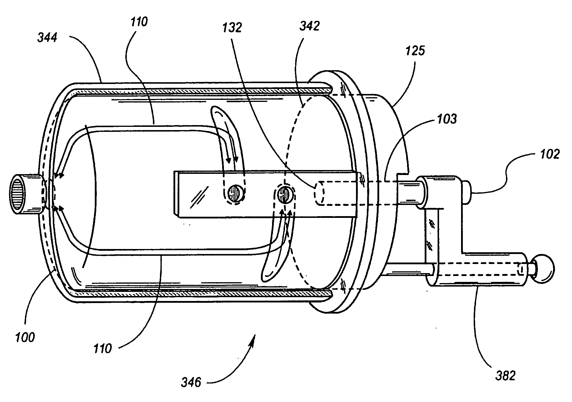
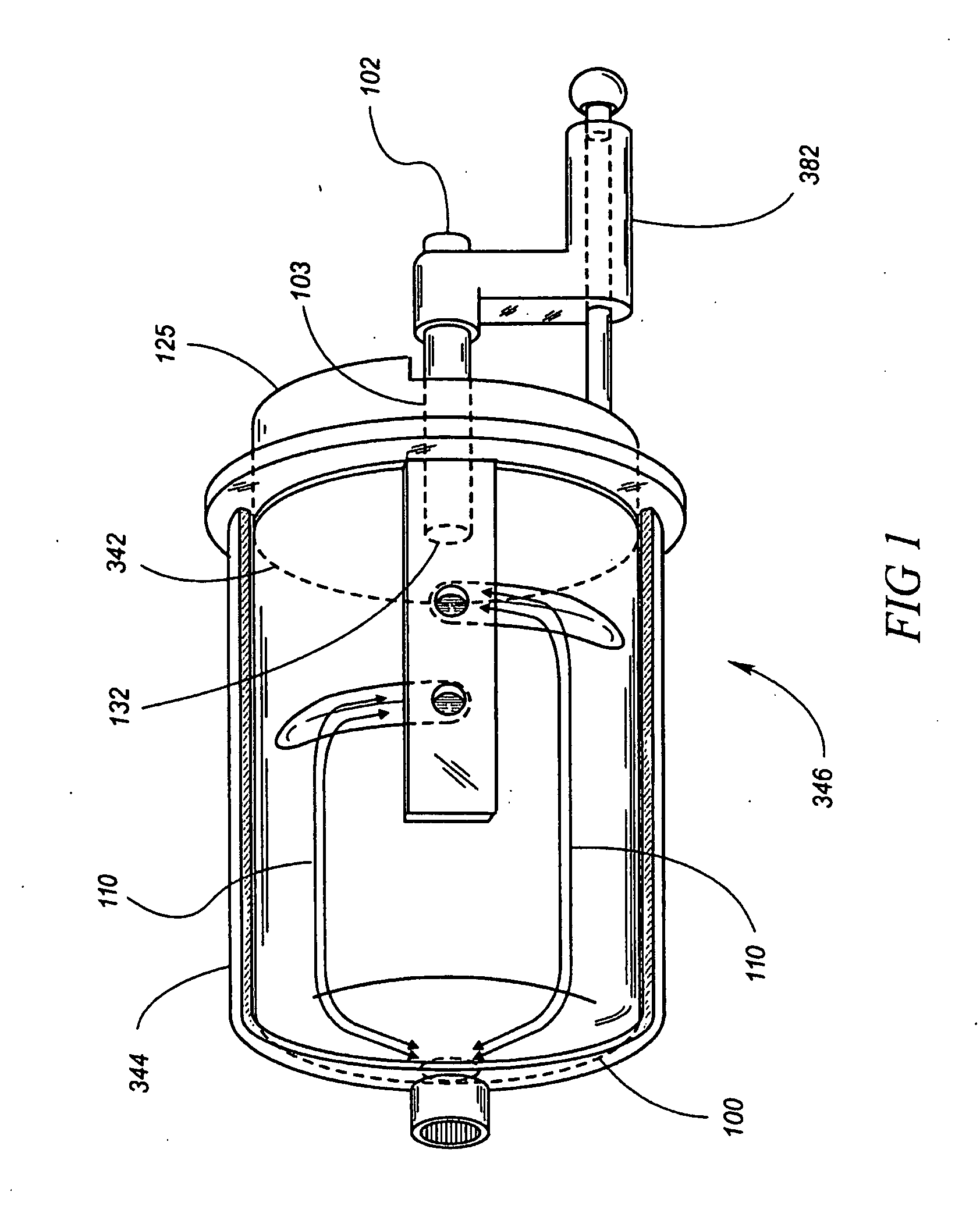
[0045]A first aspect of invention, as seen in FIG. 1, is a valve (346) for use in aircraft. One embodiment of the valve (346) includes a body (344) and a seat (342) comprising a selective interrupter (100) and an arm (102), wherein the arm (102) is connected to a first end (132) of the selective interrupter (100). The selective interrupter (100) is positioned inside the body (344) for rotation therein. A flow arrangement (110) exists between the selective interrupter (100) and the body (344). A bonnet (125) connects to the body (344) and the bonnet (125) is also in contact with the first end (132) of the selective interrupter (100). An actuator (382) is movably connected to the arm (102), and the arm (102) extends through a bonnet hole (103) in the bonnet (125).

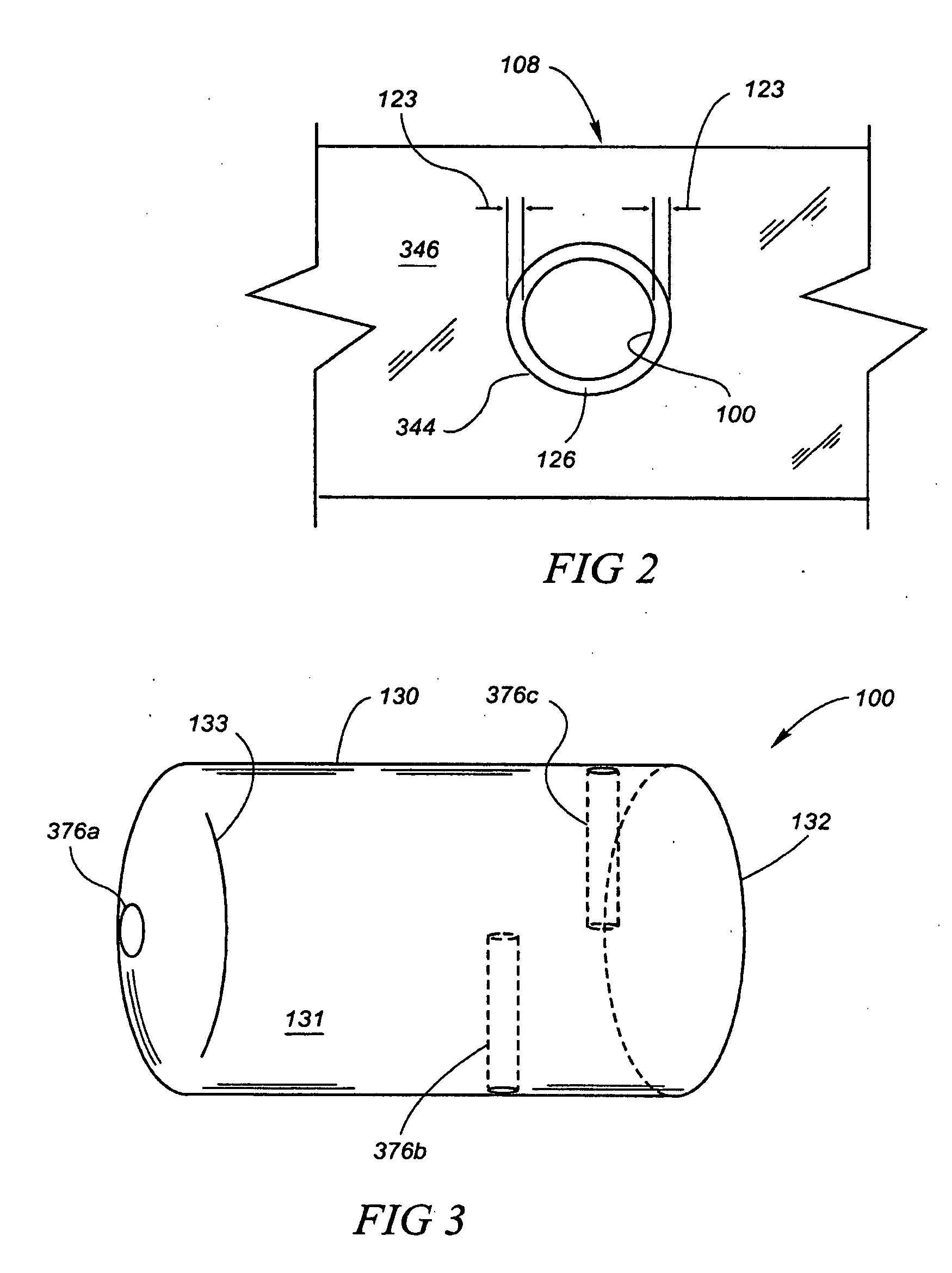
[0046]A further embodiment, as shown in FIG. 2, includes the valve (346) being installed into an aircraft instrument panel (108). A still further embodiment includes the valve (346) being installed into a standard hole within...


PUM


Abstract

A valve for use in aircraft comprises a body, a selective interrupter positioned inside the body for rotation therein, a flow arrangement between the selective interrupter and the body, a bonnet connected to the body and in contact with the selective interrupter, an arm extending through the bonnet and connected to the selective interrupter, and an actuator movably connected to the arm.

Description

CROSS-REFERENCE TO RELATED APPLICATIONS[0001]This is a divisional application of pending U.S. patent application Ser. No. 09 / 612,354, filed Jul. 7, 2000 and entitled “Aviatorial Valve Assembly”, hereby incorporated herein by reference.BACKGROUND OF THE INVENTION[0002]Acrobatic and mock emergency maneuvers place undue stress on the pneumatic gyroscopes within aircraft instrumentation. Most of the time, the gyroscopes in aircraft instrumentation are unaccustomed to withstanding routine acrobatic and mock emergency maneuvers. Because extremes in pitch and roll can damage the flight instruments' gimbals and bearings, common practice has been to disconnect the instrumentation's driver source prior to flight. This practice makes it impossible to return to instrument flight should nighttime or inclement weather arise prior to landing. Further, opening the instrument air system may allow airborne contaminants to harm the delicate gyroscopic instruments. Another common practice during testin...

Claims


Application Information

Patent Timeline
Patent Type & Authority Applications(United States)
IPC IPC(8): F16K99/00B64D43/00F16K11/085G01C19/26
CPCB64D43/00Y10T74/1218G01C19/26F16K11/0853Y10T137/6906Y10T137/86493
Inventor PARRISH, ROB G.
Owner PARRISH ROB G
Why Eureka
Try Eureka