System and method for testing tubular well products

a technology for tubular well products and systems, applied in the field of downhole applications, can solve the problems of tubular ovalisation, stress on tubular well products, and detrimental effect on well products, and achieve the effect of facilitating the design and construction of components

Inactive Publication Date: 2008-07-10
SCHLUMBERGER TECH CORP
View PDF5 Cites 25 Cited by
  • Summary
  • Abstract
  • Description
  • Claims
  • Application Information

AI Technical Summary

Benefits of technology

[0004]In general, the present invention provides a system and method for evaluating a wellbore tubular member under simulated well conditions. The evaluation is accomplished by mounting the wellbore tubular to a fixture and subjecting the wellbore tubular to a variety of predetermined conditions simulating potential downhole environments. The ability to pretest a variety of tubular well products facilitates the design and construction of components and systems better able to withstand challenging environmental conditions when placed into operation in a wellbore.

Problems solved by technology

In some oilfield environments, the tubular well products are subjected to stresses that can have a detrimental effect on the well products.
The stresses can be caused by zonal slip, reservoir compaction, gravel pack packers, liner overlap, cement voids, thermal gradients, and other well conditions that can lead to tubular ovalisation and other detrimental effects, and can result in catastrophic failure.
For example, reservoir compaction can be severe enough to cause failure of the tubular well product through tension, buckling, collapse, and / or shearing.
In some environments, shear loading causes severe localized deformation of the tubular well product, e.g. deformation of well casing.
Some subsurface shale regions, for example, are prone to shift horizontally as reservoirs undergo vertical compaction or subsidence.
The shifting of the reservoir can place a variety of tubular well products under high loads that ultimately lead to damage or failure of the well product.
However, no suitable approach exists for preliminary testing of the various tubular well products to adequately determine the reaction to such loads.

Method used


Image

  • System and method for testing tubular well products
  • System and method for testing tubular well products
  • System and method for testing tubular well products

Examples


Embodiment Construction

[0011]In the following description, numerous details are set forth to provide an understanding of the present invention. However, it will be understood by those of ordinary skill in the art that the present invention may be practiced without these details and that numerous variations or modifications from the described embodiments may be possible.

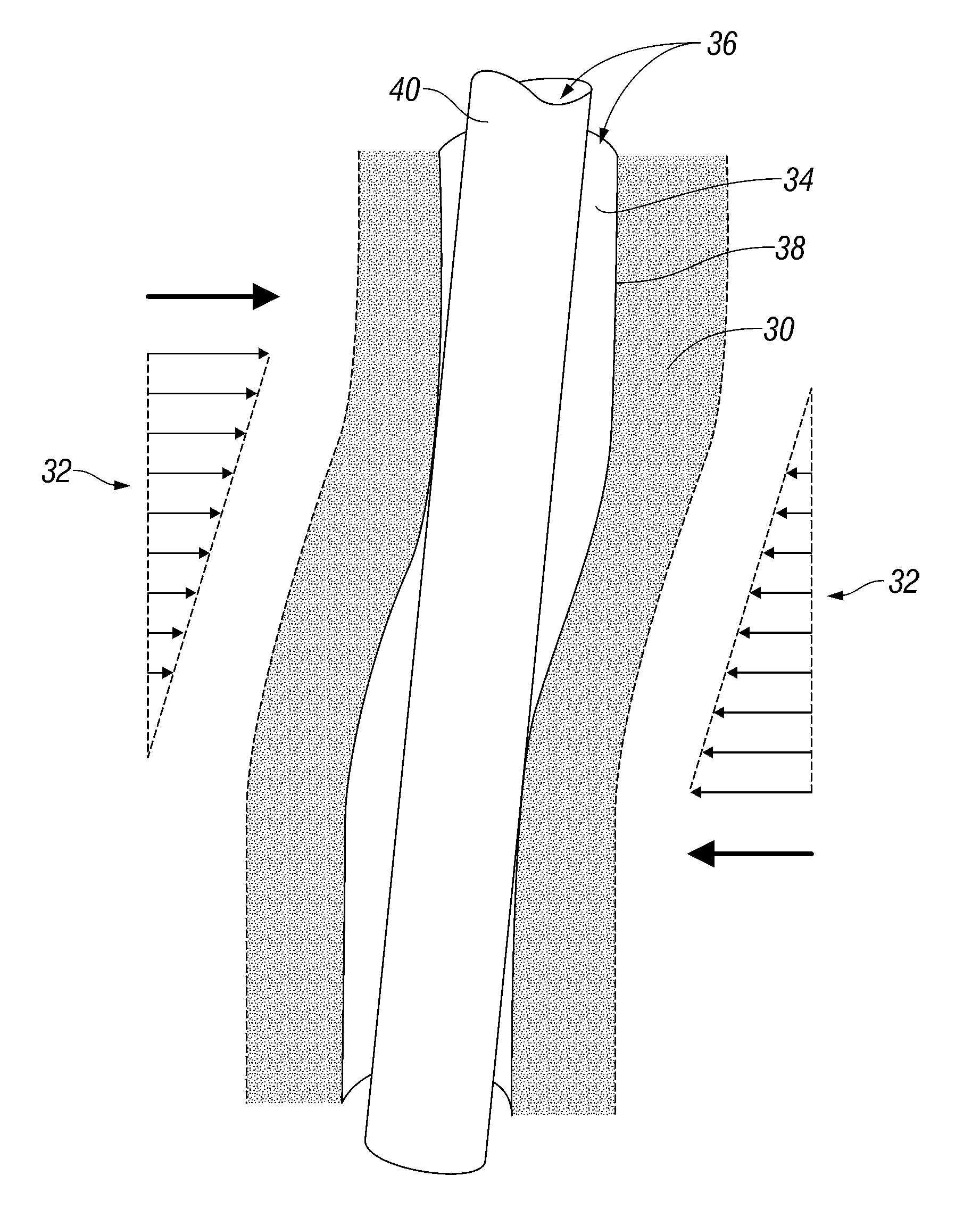
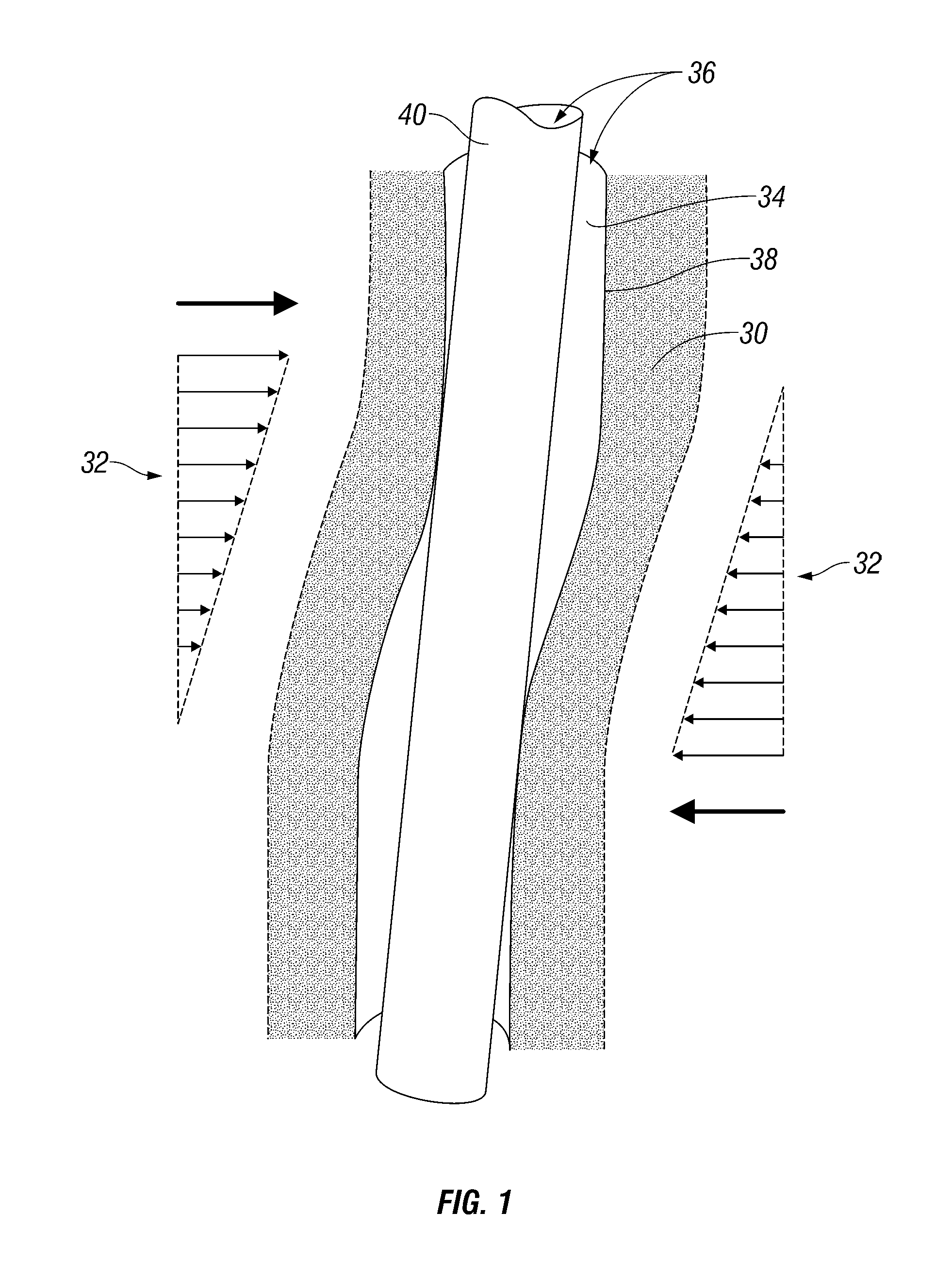
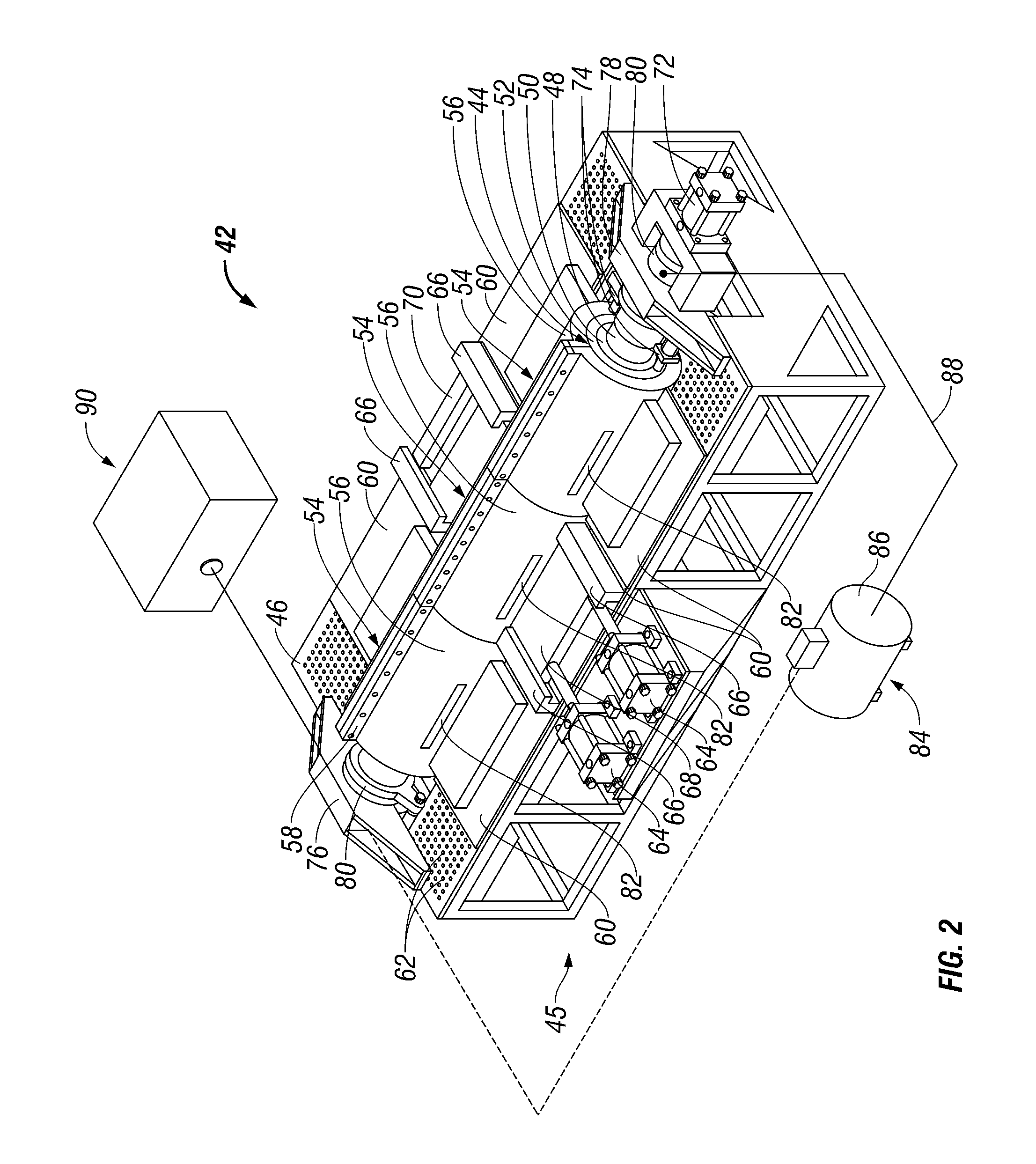
[0012]The present invention generally relates to a system and methodology for evaluating tubulars used in well-related applications, such as hydrocarbon production applications. Various wellbore tubulars, e.g. completions system tubulars, can be evaluated prior to deployment into a wellbore to mitigate detrimental effects on the tubular components during use in the wellbore environment. The ability to pretest or pre-evaluate the tubular system or component design helps to, for example, mitigate component ovalisation and shear failures that can result from stresses induced by zonal slip, reservoir compaction / subsidence, gravel pack packers, ...


PUM


Abstract

A technique enables testing of a wellbore tubular under simulated well conditions. The wellbore tubular is mounted in a fixture for testing. Controllable systems are used to subject the wellbore tubular to a variety of predetermined conditions simulating potential downhole environments. The controllable systems include manipulators able to place the wellbore tubular under predetermined load, displacement, temperature, and pressure conditions.

Description

CROSS-REFERENCE TO RELATED APPLICATIONS[0001]This application claims priority to U.S. Provisional Application No. 60 / 884,067, filed Jan. 9, 2007. This application is related to U.S. Provisional Application No. 60 / 884,075, also filed Jan. 9, 2007, and to the regular patent application filed of even date herewith claiming priority therefrom.BACKGROUND OF THE INVENTION[0002]In many downhole applications, various tubular products and tubular product materials are used in well-related applications. The tubular well products are deployed into wellbores drilled into the earth through reservoirs that contain production fluid, such as oil or gas. In some oilfield environments, the tubular well products are subjected to stresses that can have a detrimental effect on the well products. The stresses can be caused by zonal slip, reservoir compaction, gravel pack packers, liner overlap, cement voids, thermal gradients, and other well conditions that can lead to tubular ovalisation and other detri...

Claims


Application Information

Patent Timeline
Patent Type & Authority Applications(United States)
IPC IPC(8): E21B47/10
CPCE21B17/00G01N3/22E21B41/00
Inventor JACOBS, SCOTTHAMMAMI, AHMEDYAKIMOSKI, TODD
Owner SCHLUMBERGER TECH CORP
Why Eureka
Try Eureka