
Method and circuit for curvature correction in bandgap references with asymmetric curvature

Active Publication Date: 2008-07-10
TEXAS INSTR INC
View PDF8 Cites 12 Cited by
  • Summary
  • Abstract
  • Description
  • Claims
  • Application Information

AI Technical Summary

Benefits of technology

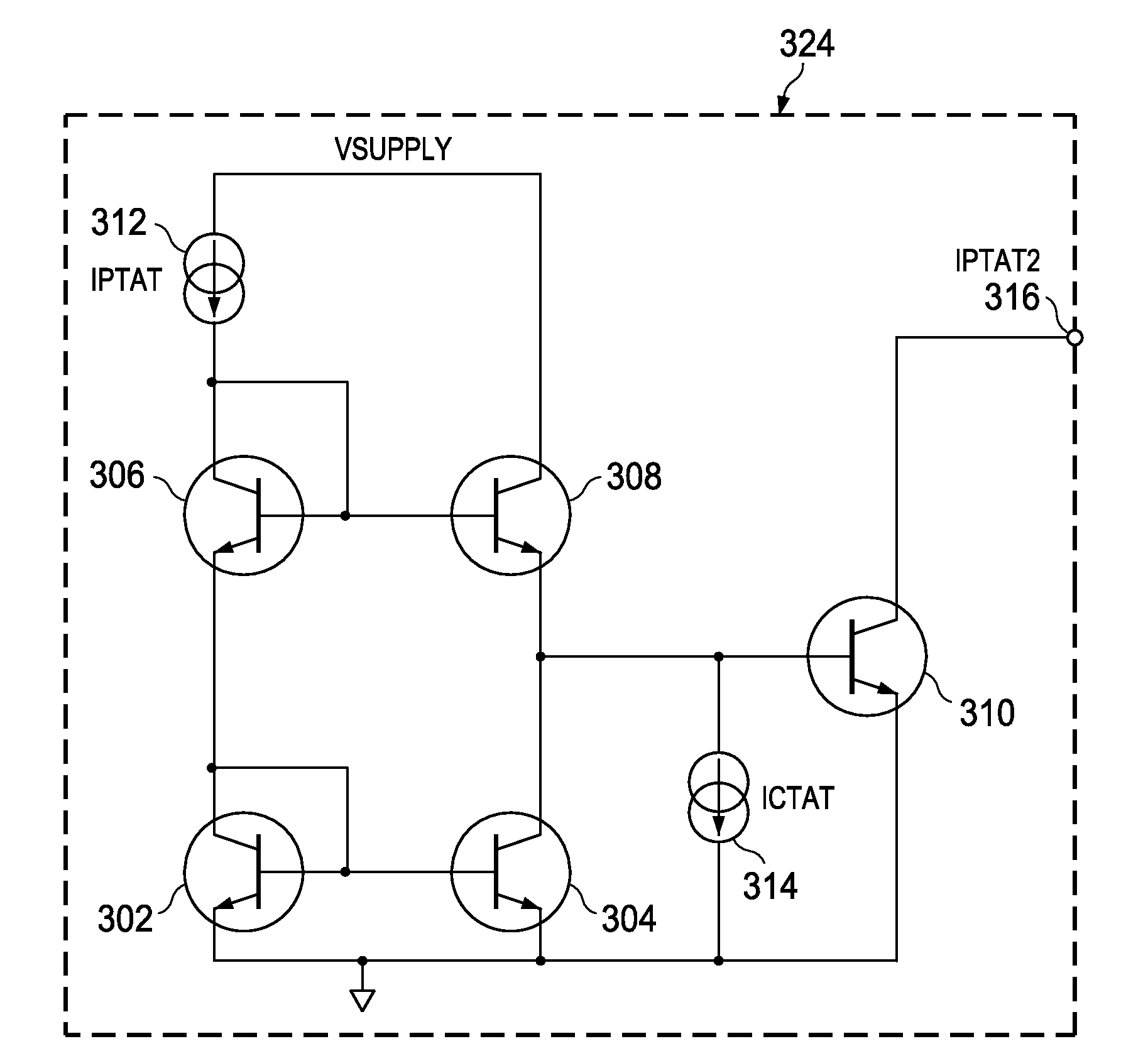
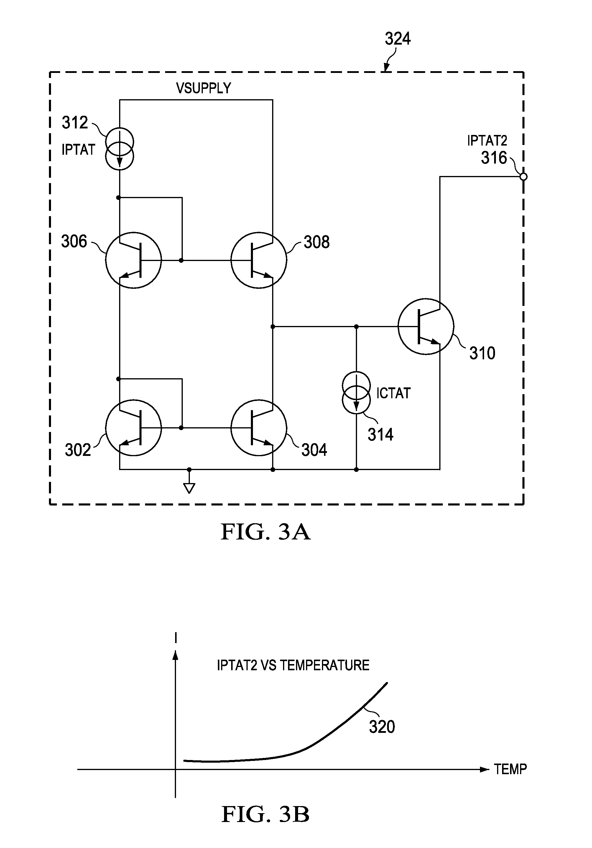
[0008]The invention provides a method and apparatus for generating a correction current in a bandgap reference circuit, wherein the correction current is, in one embodiment, small at some nominal temperature Tn, increasing in a non-linear or 1/T manner as temperature decreases below Tn. This correction current is generated in a circuit having a known architecture which has as inputs both a PTAT current and a CTAT current. Whereas in the prior art such currents in this architecture result in a current PTAT2 (which will also be referred to herein as IPTAT2), in the embodiment to be described, a CTAT correction current (ICTAT2) is generated by reversing the PTAT and CTAT inputs to the same circuit topology. The resulting correction current is injected to a node in the bandgap reference circuit which converts the current into a corresponding voltage correction. This corre

Problems solved by technology

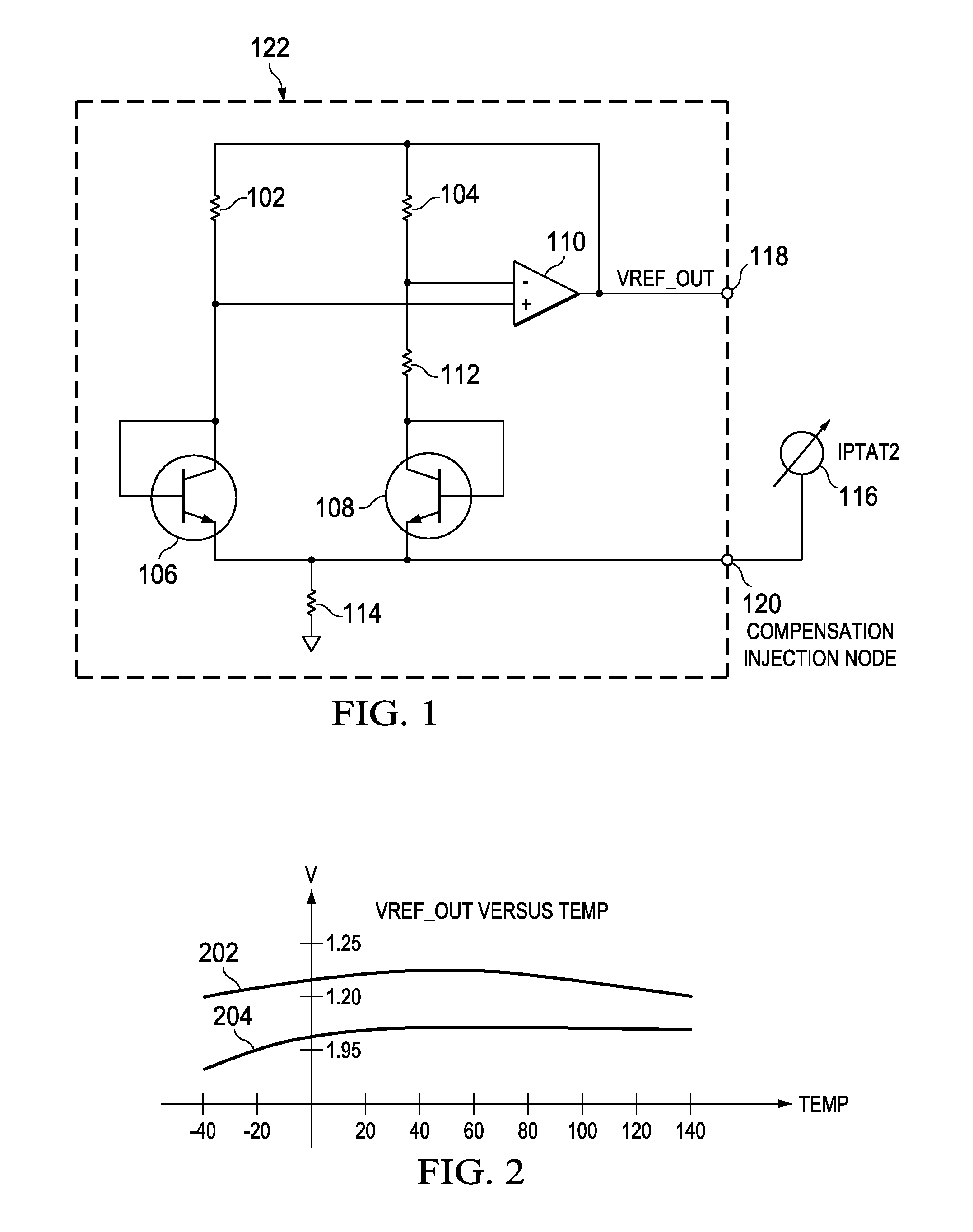
There remains, however, a residual temperature effect on voltage which, in theory, introduces an increasingly negative error as temperature varies either above or below the nominal operating temperature (Tn).
In some actual integrated bandgap reference circuits, however, the uncompensated voltage versus temperature relationship is not the parabolic curve predicted by theory.
Differences in processes, structures, and other variables lead, in many cases, to a voltage having little error above a nominal temperature, but pronounced curvature (voltage error increasing as the square of change in temperature) as temperature decreases from nominal.
Applying known compensation to such circuits has a smaller than desired effect on error below Tn, and may increase rather than reduce the error above Tn.

Method used


Image

  • Method and circuit for curvature correction in bandgap references with asymmetric curvature
  • Method and circuit for curvature correction in bandgap references with asymmetric curvature
  • Method and circuit for curvature correction in bandgap references with asymmetric curvature

Examples


Embodiment Construction

[0019]In FIG. 1 (prior art), the output of amplifier 110 is coupled to a first terminal of resistors 102 and 104 and to output terminal 118. The second terminal of resistor 102 is coupled to the non-inverting input of amplifier 110 and to the collector and base of transistor 106. The second terminal of resistor 104 is coupled to the inverting input of amplifier 110 and to a first terminal of resistor 112. The second terminal of resistor 112 is coupled to the collector and base of transistor 108. The emitters of both transistor 106 and transistor 108 are coupled together, and are coupled to the first terminal of resistor 114, terminal 120, and current source 116. The second terminal of 114 is coupled to ground.

[0020]In operation, because resistor 102 and resistor 104 are substantially equal, when equal currents flow through both resistors the voltage drops across them are substantially equal. Since the currents flowing into the inputs of amplifier 110 are typically negligible, the cu...


PUM


Abstract

A non-linear correction current ICTAT2 (current complementary to the square of absolute temperature) is generated from a current IPTAT (current proportional to absolute temperature) and a current ICTAT (current complementary to absolute temperature), both modified in a circuit having a topology and components which capitalize on the logarithmic relationship between transistor collector current and base-emitter voltage. The resulting ICTAT2 current (current complementary to the square of absolute temperature) is injected into a node of a bandgap reference circuit to compensate for non-linear temperature effects on output voltage. A more general correction circuit generates both IPTAT2 and ICTAT2, and applies each to a respective multiplier which, in a preferred embodiment, is a current DAC configured as a multiplier. Control inputs CTL1 and CTL2 to respective multipliers set the amplitudes of the modified IPTAT2 and ICTAT2 output currents, which are then summed to generate the compensating current Icomp which is injected to the appropriate node in the bandgap reference circuit as described above. By adjusting the relative amplitudes of the IPTAT2 and ICTAT2 currents, a wide range of compensating current versus voltage curves is produced, allowing the optimization of a wide range of bandgap reference circuits. An optimal value for CTL1 is determined by holding CTL2 constant, then measuring curvature at a plurality of CTL1 values. That CTL1 value closest to the interpolated value at which curvature is minimized is then used.

Description

BACKGROUND OF THE INVENTION[0001]1. Field of the Invention[0002]This invention relates generally to temperature compensation of bandgap voltage references, and more specifically to correction of non-linear output voltage versus temperature errors by generating and applying a correction signal or a superposition of a plurality of correction signals having a second or higher order relationship to temperature, proportional to absolute temperature (PTAT) or complementary to absolute temperature (CTAT).[0003]2. Description of the Related Art[0004]Bandgap references such as that using a Brokaw architecture typically generate an output voltage which is the sum of 1) the voltage drop across a semiconductor junction, having a temperature coefficient complementary to absolute temperature (CTAT), and 2) a voltage having a temperature coefficient proportional to absolute temperature (PTAT); wherein the temperature coefficients of the CTAT and PTAT voltages have approximately the same magnitude ...

Claims


Application Information

Patent Timeline
IPC IPC(8): G05F3/16G05F1/10
CPCG05F3/30
Inventor OBERHUBER, RALPHBROUSE, KEITH
Owner TEXAS INSTR INC
Learn More