
Edge-Oriented Interpolation Method and System for a Digital Image

a digital image and edge-oriented interpolation technology, applied in the field of digital image processing, can solve the problems of image blurring artifacts, less computation and low cost of bilinear interpolation, and the failure of interpolation to settle the blurring or jagging of edges, etc., to achieve accurate color rendering of digital images.

Inactive Publication Date: 2008-07-10
HIMAX TECH LTD
View PDF3 Cites 11 Cited by
  • Summary
  • Abstract
  • Description
  • Claims
  • Application Information

AI Technical Summary

Benefits of technology

[0008]An objective of the present invention is to provide an adaptive edge-oriented interpolation method for an image and a system thereof. In particular, the region in which a destination pixel is located is identified as a smooth region, a text region or an edge region, and the interpolation function assigned to the identified region is applied in the destination pixel color value calculation. As a result, accurate color rendering of a digital image is achieved, even in the presence of an edge portion that has an edge line with an arbitrary tangent direction.

Problems solved by technology

Yet such interpolation fails to settle the blurring or the jagging of edges as a basic problem in image interpolation so far.
Bilinear interpolation has less computation and a low cost, but results in images with unpleasant blurring artifacts, especially when displayed on a large-scale display such as a 42 inch LCD panel or a 42 inch plasma panel.
In contrast, bi-cubic interpolation is much more complicated and costly.

Method used


Image

  • Edge-Oriented Interpolation Method and System for a Digital Image
  • Edge-Oriented Interpolation Method and System for a Digital Image
  • Edge-Oriented Interpolation Method and System for a Digital Image

Examples


Embodiment Construction

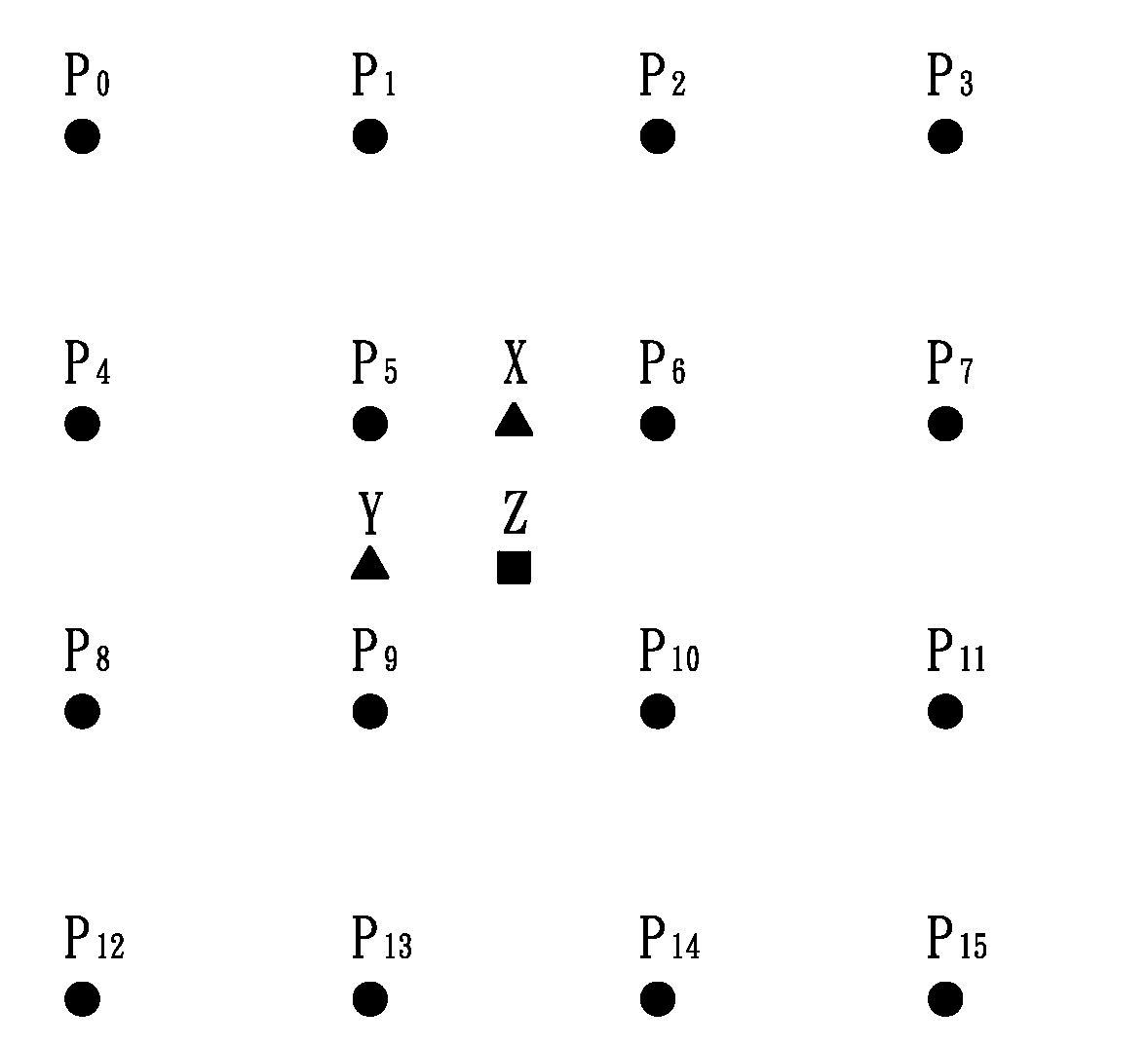
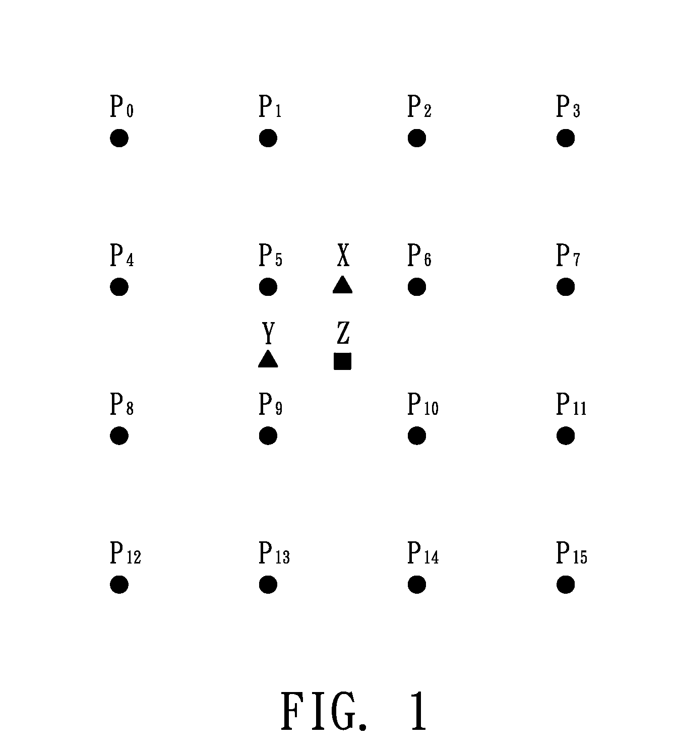
[0014]FIG. 1 is an illustration of a matrix of sixteen reference pixels P0-P15 and three destination pixels X-Z on a digital image. As shown in FIG. 1, sixteen reference pixels P0-P15 arranged into a 4-by-4 matrix are selected from the digital image for interpolation of three destination pixels X-Z. The destination pixel X is expected to be inserted between two neighboring pixels P5 and P6 along a transversal direction, the destination pixel Y is expected to be inserted between two neighboring pixels P5 and P9 along a longitudinal direction, and the destination pixel Z is expected to be inserted between two neighboring pixels P5 and P10 along a diagonal direction.

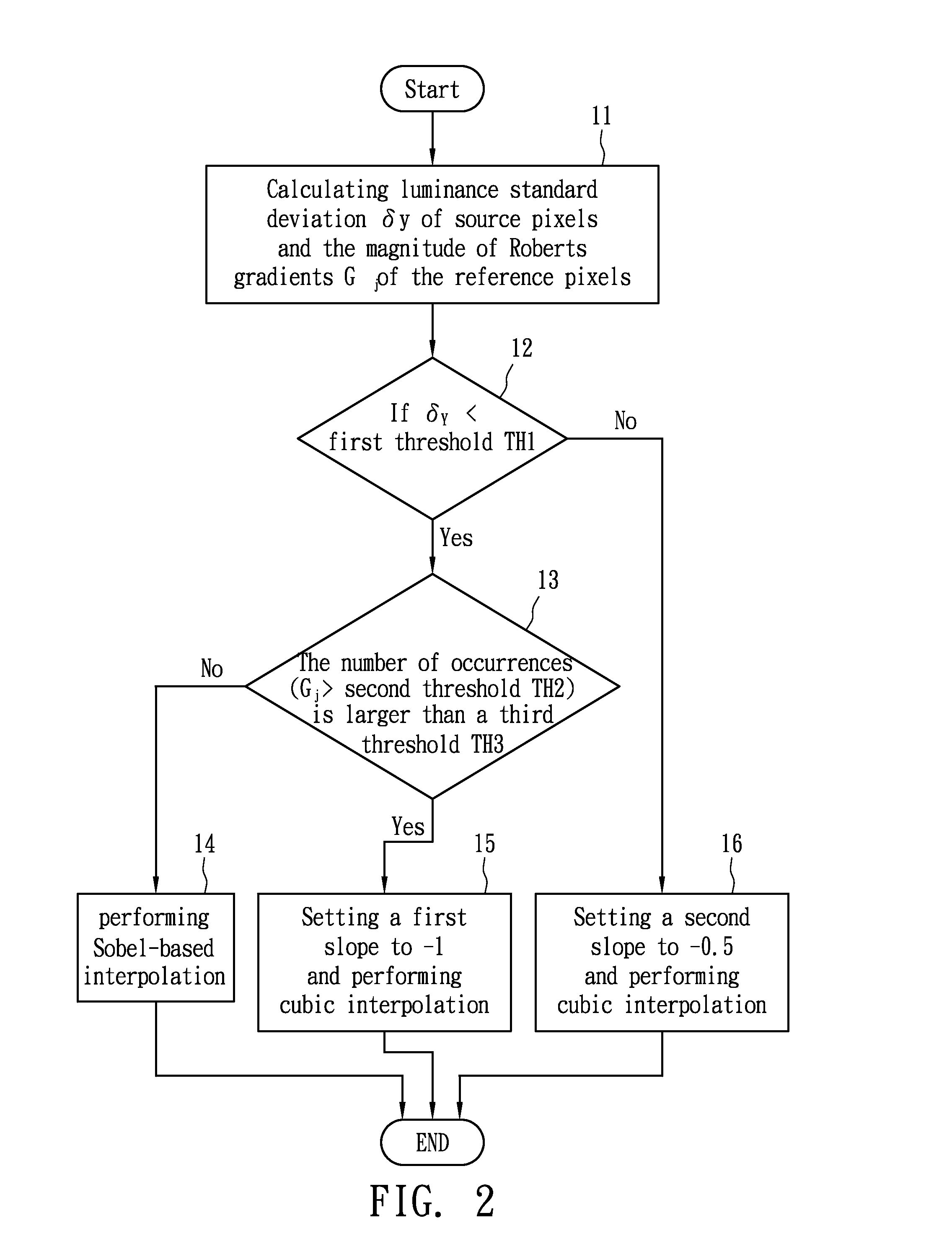
[0015]FIG. 2 is a flow chart showing an edge-oriented interpolation method for the digital image in accordance with a preferred embodiment of the invention. Before interpolation for a destination pixel is performed, the region in which the destination pixel is located needs to be identified. Steps 11-13 are used to determin...


PUM


Abstract

An edge-oriented interpolation method is used for enlarging a source image. The region in which each destination pixel in an enlarged image is located is identified as a smooth region, a text region or an edge region, and Sobel edge detection for two adjacent pixels around the destination pixel is performed to obtain two Sobel gradients. When the destination pixel is located in a smooth region, cubic convolution interpolation is performed for the destination pixel with a first slope. When the destination pixel is located in a text region, cubic convolution interpolation is performed for the destination pixel with a second slope. When the destination pixel is located in an edge region, Sobel-based interpolation for the destination pixel is performed with the two Sobel gradients.

Description

BACKGROUND OF THE INVENTION[0001]1. Field of the Invention[0002]The present invention relates to digital image processing, and more particularly relates to an edge-oriented interpolation method and system for a digital image, which is especially useful to enhance image interpolation at edge portions of the digital image.[0003]2. Description of the Related Art[0004]Linear interpolation such as bilinear and bi-cubic interpolation is very fundamental to many digital image processing operations such as scaling, rotation, translation and geometric correction. Yet such interpolation fails to settle the blurring or the jagging of edges as a basic problem in image interpolation so far.[0005]Bilinear interpolation has less computation and a low cost, but results in images with unpleasant blurring artifacts, especially when displayed on a large-scale display such as a 42 inch LCD panel or a 42 inch plasma panel. This is mostly due to the color averaging in bilinear interpolation.[0006]In cont...

Claims


Application Information

Patent Timeline
IPC IPC(8): G09G5/00
CPCG06T3/403
Inventor WANG, HSIN CHUNG
Owner HIMAX TECH LTD
Learn More