

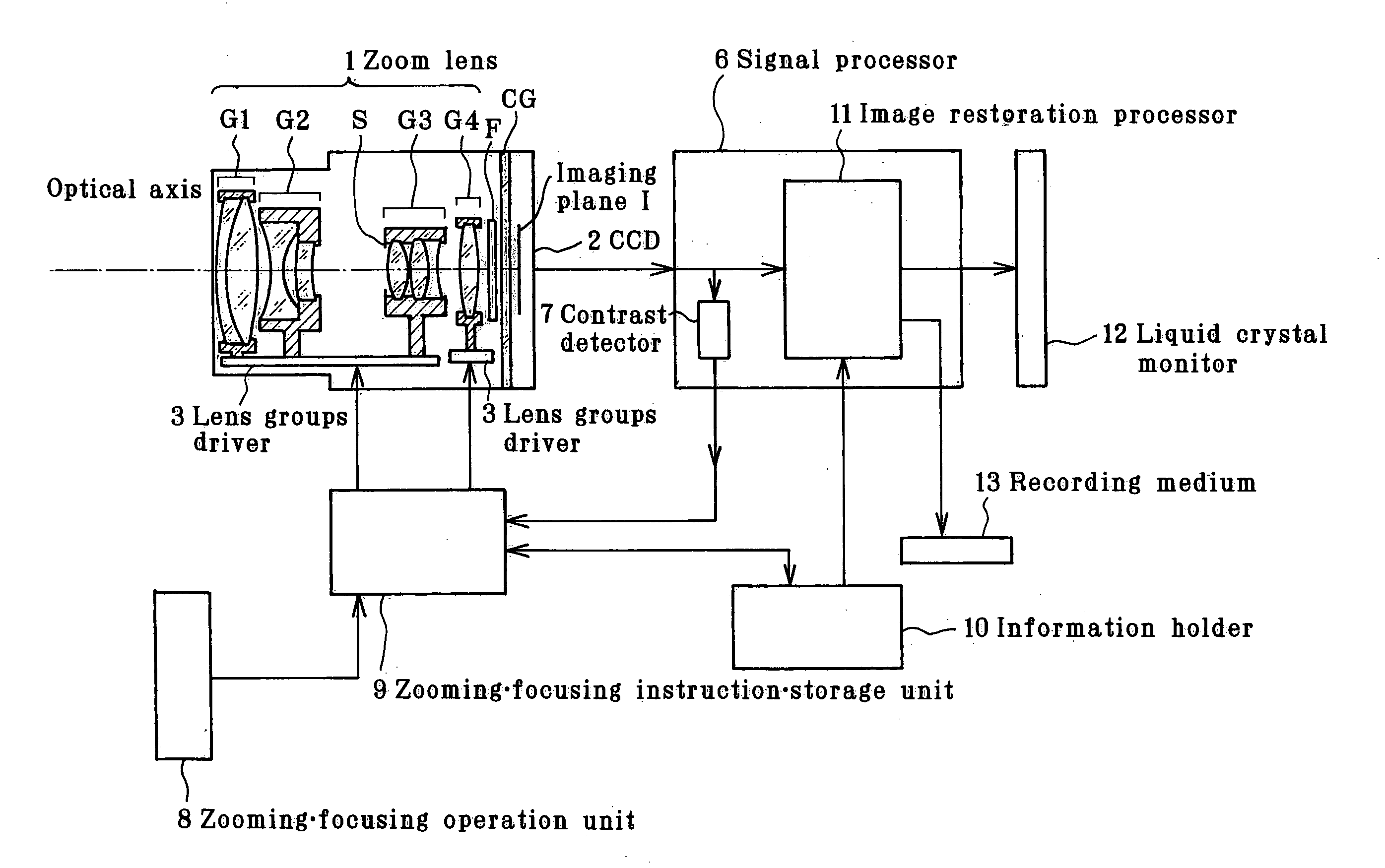
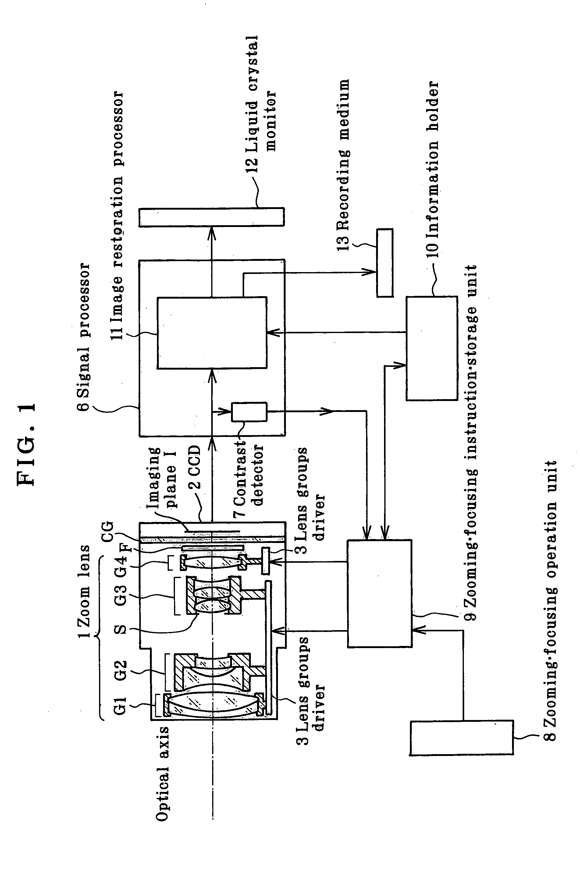
Imaging apparatus adapted to implement electrical image restoration processing
a technology of electrical image and restoration processing, applied in the field of imaging equipment, can solve the problems of poor image quality, more blurred images taken by imaging devices, and bulky optical systems, and achieve the effects of reducing the size of the apparatus, good image quality, and effective us
- Summary
- Abstract
- Description
- Claims
- Application Information
AI Technical Summary
Benefits of technology
Problems solved by technology
Method used
Image

Examples
example 1
[0233]
r1 = 13.941d1 = 0.80nd1 = 1.92286νd1 = 20.88r2 = 10.260d2 = 3.33nd2 = 1.58233νd2 = 59.40r3 = −45.370 (Aspheric)d3 = (Variable)r4 = −13.175 (Aspheric)d4 = 0.90nd3 = 1.83481νd3 = 42.71r5 = 4.180 (Aspheric)d5 = 0.80r6 = 5.674d6 = 2.07nd4 = 1.94595νd4 = 17.98r7 = 9.459d7 = (Variable)r8 = ∞ (Stop)d8 = 0.00r9 = 4.390 (Aspheric)d9 = 1.60nd5 = 1.51573νd5 = 64.10r10 = −10.248 (Aspheric)d10 = 0.10r11 = 7.016d11 = 2.00nd6 = 1.77250νd6 = 49.60r12 = −4.424d12 = 0.40nd7 = 1.74950νd7 = 35.28r13 = 3.071d13 =(Variable)r14 = 27.505 (Aspheric)d14 = 1.87nd8 = 1.74330νd8 = 49.33r15 = −21.289d15 =(Variable)r16 = ∞d16 = 0.50nd9 = 1.51633νd9 = 64.14r17 = ∞d17 = 0.50r18 = ∞d18 = 0.50nd10 = 1.51633νd10 = 64.14r19 = ∞d19 = 0.36r20 = ∞ (Imaging plane)Aspherical Coefficients3rd surfaceK = 0.000A4 = 4.12725 × 10⁻⁵A6 = 6.93194 × 10⁻⁸A8 = −5.03992 × 10⁻⁹A10 = 4.54452 × 10−114th surfaceK = 0.232A4 = 3.06592 × 10⁻⁴A6 = 2.98441 × 10⁻⁵A8 = −1.52860 × 10⁻⁶A10 = 2.61101 × 10−85th surfaceK = −0.394A4 = −3.82320 × 1...
example 2
[0234]
r1 = 17.576 (Aspheric)d1 = 3.10nd1 = 1.49700νd1 = 81.54r2 = −34.901 (Aspheric)d2 = (Variable)r3 = −12.242 (Aspheric)d3 = 0.80nd2 = 1.80610νd2 = 40.92r4 = 5.092 (Aspheric)d4 = 1.00r5 = 7.035d5 = 1.76nd3 = 1.92286νd3 = 20.88r6 = 13.136d6 = (Variable)r7 = ∞ (Stop)d7 = 0.06r8 = 7.206 (Aspheric)d8 = 1.80nd4 = 1.77250νd4 = 49.60r9 = −16.361 (Aspheric)d9 = 0.10r10 = 7.946d10 = 1.60nd5 = 1.72916νd5 = 54.68r11 = 72.753d11 = 0.70nd6 = 1.84666νd6 = 23.78r12 = 3.957d12 =(Variable)r13 = 9.054 (Aspheric)d13 = 1.80nd7 = 1.69895νd7 = 30.13r14 = 60.902 (Aspheric)d14 =(Variable)r15 = ∞d15 = 0.81nd8 = 1.54771νd8 = 62.84r16 = ∞d16 = 0.57r17 = ∞d17 = 0.47nd9 = 1.51633νd9 = 64.14r18 = ∞d18 = 0.59r19 = ∞ (Imaging plane)Aspherical Coefficients1st surfaceK = 0.000A4 = 5.04557 × 10⁻⁵A6 = 4.78766 × 10⁻⁸A8 = −3.29005 × 10⁻⁹A10 = 7.61743 × 10−112nd surfaceK = 0.000A4 = 1.02541 × 10⁻⁴A6 = −6.32316 × 10⁻⁷A8 = 4.94778 × 10⁻⁹A10 = −4.47738 × 10−123rd surfaceK = 0.000A4 = 4.38031 × 10⁻⁴A6 = 6.87497 × 10⁻⁶A8 = ...
example 3
[0235]
r1 = 325.405d1 = 1.00nd1 = 2.00069νd1 = 25.46r2 = 27.199d2 = 0.10r3 = 15.067 (Aspheric)d3 = 4.27nd2 = 1.77377νd2 = 47.17r4 = −38.403 (Aspheric)d4 = (Variable)r5 = −16.420 (Aspheric)d5 = 0.80nd3 = 1.80610νd3 = 40.92r6 = 7.005 (Aspheric)d6 = 3.04r7 = 20.739d7 = 1.78nd4 = 1.94595νd4 = 17.98r8 = 160.814d8 = (Variable)r9 = ∞ (Stop)d9 = 0.10r10 = 6.981 (Aspheric)d10 = 3.81nd5 = 1.58913νd5 = 61.14r11 = −36.565 (Aspheric)d11 = 0.10r12 = 7.062 (Aspheric)d12 = 2.72nd6 = 1.80610νd6 = 40.92r13 = −57.657d13 = 0.52nd7 = 2.00069νd7 = 25.46r14 = 4.263d14 =(Variable)r15 = 11.540 (Aspheric)d15 = 2.30nd8 = 1.74330νd8 = 49.33r16 = 62.647d16 =(Variable)r17 = ∞d17 = 0.50nd9 = 1.54771νd9 = 62.84r18 = ∞d18 = 0.60r19 = ∞d19 = 0.60nd10 = 1.51633νd10 = 64.14r20 = ∞d20 = 0.36r21 = ∞ (Imaging plane)Aspherical Coefficients3rd surfaceK = −0.413A4 = −1.62992 × 10⁻⁵A6 = −1.56441 × 10⁻⁷A8 = 2.11010 × 10⁻⁹A10 = −8.78346 × 10−124th surfaceK = −9.142A4 = −5.96973 × 10⁻⁷A6 = −4.80555 × 10⁻⁸A8 = 1.47942 × 10⁻⁹A10 =...
PUM
 Abstract
Description
Claims
Application Information