Dental suction appliance

Inactive Publication Date: 2008-07-10
KANAS DAVID C
View PDF2 Cites 21 Cited by
  • Summary
  • Abstract
  • Description
  • Claims
  • Application Information

AI Technical Summary

Benefits of technology

[0023]Another aspect is a dental apparatus comprising an aspirator having an aspiration tube portion at its proximal end and a tongue deflector portion at its distal end, wherein tongue deflector portion is configured to be positioned at near a treatment location in a patient's mouth and extends laterally from an axis of the aspiration tube portion to control movement of the patient's tongue at the location. The aspiration tube section comprises an aspiration channel extending from the proximal end to the tongue deflector for aspirating liquid

Problems solved by technology

A common problem for dentists and dental hygienists performing surgery and other dental procedures is the removal of saliva generated by the patient, removal of water used to cool high speed drills, and removal of water and other liquids used in connection with certain procedures.
In addition, the patient's jaw muscles become tense and it be difficult for the patient to maintain the mouth in an open position.
However, this particular device is not suited for use by patients who are missing teeth and cannot effectively clamp the bite block in place and, furthermore, does not provide for deflecting the tongue away from the work area.
This device, however, does not deflect the tongue, greatly restricts the de

Method used


Image

  • Dental suction appliance
  • Dental suction appliance
  • Dental suction appliance

Examples


Example

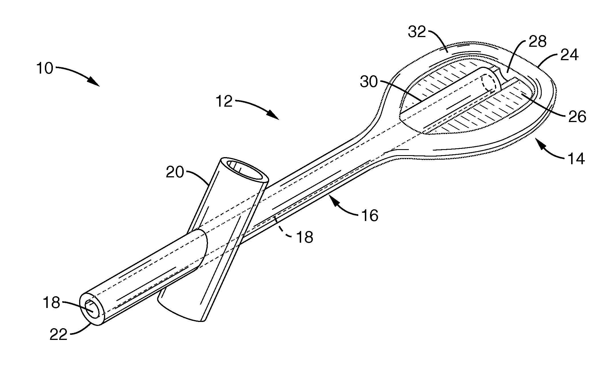
[0036]Referring more specifically to the drawings, for illustrative purposes the present invention is embodied in the apparatus generally shown in FIG. 1 through FIG. 8. It will be appreciated that the apparatus may vary as to configuration and as to details of the parts, and that the method may vary as to the specific steps and sequence, without departing from the basic concepts as disclosed herein.

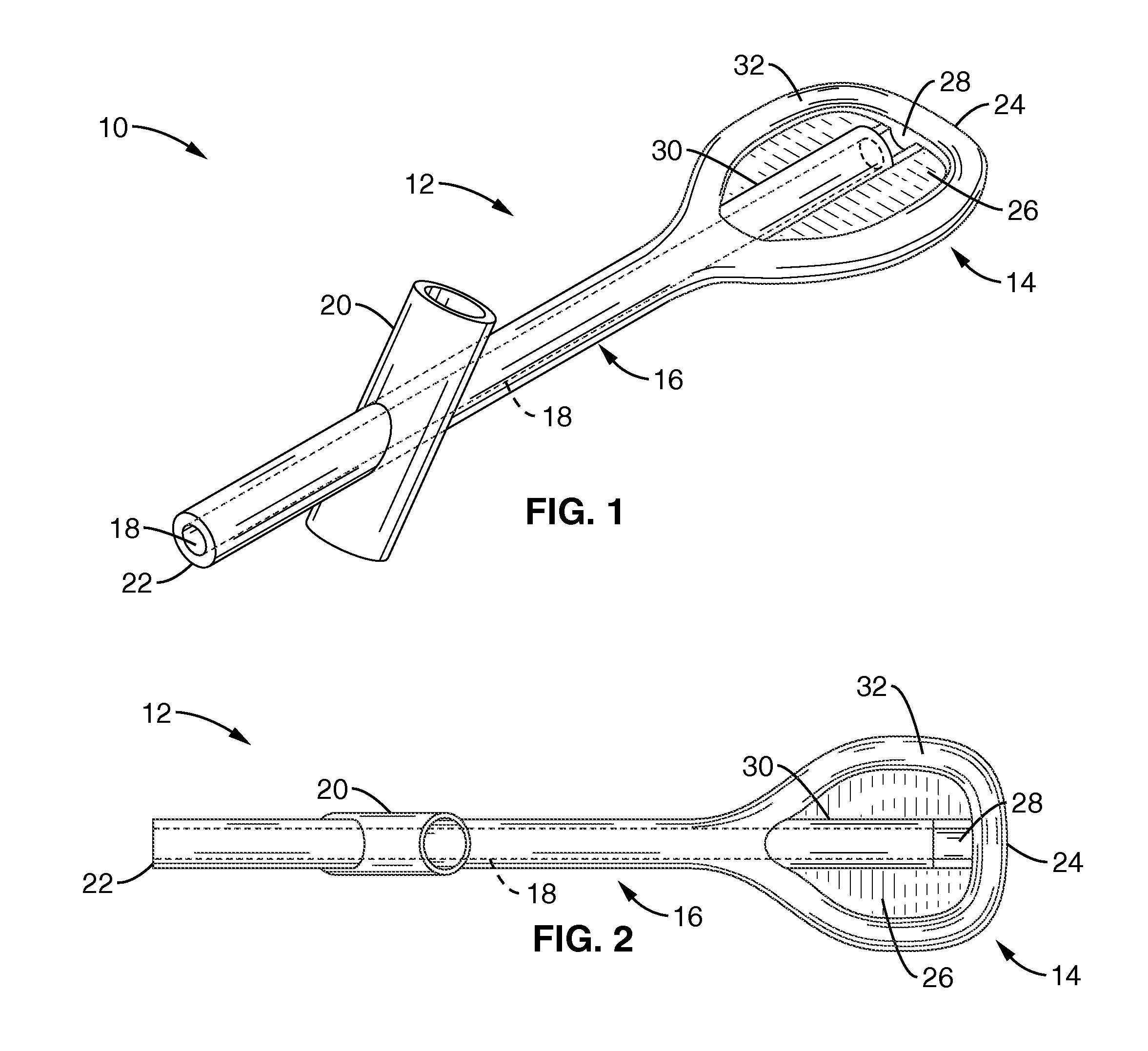
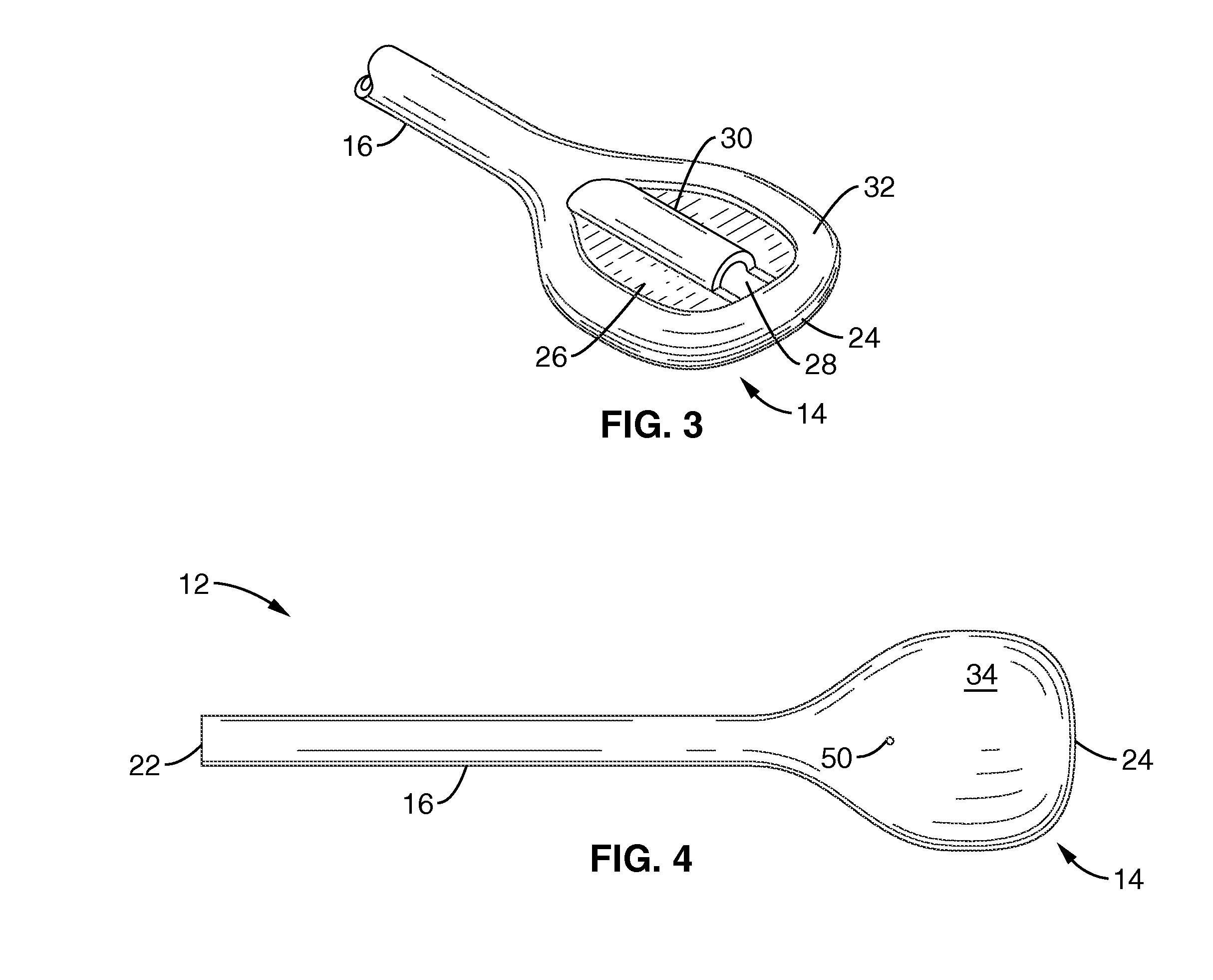
[0037]Referring to FIG. 1 through FIG. 3, the dental appliance 10 in accordance with the present invention includes an aspirator 12 having a tongue deflector 14 at its distal end 24. The aspirator 12 tapers inward from the distal end 24 to form a generally cylindrical aspiration tube 16 that terminates at a proximal end 22.

[0038]The tongue deflector 14 and aspirator tube 16 form a unitary, contiguous member (aspirator 12) that is preferably constructed from the same material. Preferably, the aspirator 12 is fabricated from plastic or the like material that can be plastic injection molded...


PUM


Abstract

Apparatus and methods for providing a dental appliance that functions as an aspirator and tongue deflector. The aspirator has a proximal end and a distal end configured to be positioned at near a treatment location in the mouth of the patient. A tongue deflector is disposed on the distal end of the aspirator for controlling movement of the patient's tongue at the location. An elongate aspiration tube emanates at the proximal end of the aspirator and terminates at the tongue deflector for aspirating liquids at or near the treatment location. The aspirator tube has an aspiration channel running concentrically along the aspiration tube from the proximal end to a collection recess in the tongue deflector. The dental appliance may be fabricated such that the tongue deflector and aspirator are formed as one contiguous unitary piece.

Description

CROSS-REFERENCE TO RELATED APPLICATIONS[0001]Not ApplicableSTATEMENT REGARDING FEDERALLY SPONSORED RESEARCH OR DEVELOPMENT[0002]Not ApplicableINCORPORATION-BY-REFERENCE OF MATERIAL SUBMITTED ON A COMPACT DISC[0003]Not ApplicableNOTICE OF MATERIAL SUBJECT TO COPYRIGHT PROTECTION[0004]A portion of the material in this patent document is subject to copyright protection under the copyright laws of the United States and of other countries. The owner of the copyright rights has no objection to the facsimile reproduction by anyone of the patent document or the patent disclosure, as it appears in the United States Patent and Trademark Office publicly available file or records, but otherwise reserves all copyright rights whatsoever. The copyright owner does not hereby waive any of its rights to have this patent document maintained in secrecy, including without limitation its rights pursuant to 37 C.F.R. §1.14.BACKGROUND OF THE INVENTION[0005]1. Field of the Invention[0006]This invention pert...

Claims


Application Information

Patent Timeline
IPC IPC(8): A61C17/06
CPCA61C17/043A61C17/08
Inventor KANAS, DAVID C.
Owner KANAS DAVID C
Why Eureka
Try Eureka