

Connector system for a wall installation
- Summary
- Abstract
- Description
- Claims
- Application Information
AI Technical Summary
Benefits of technology
Problems solved by technology
Method used
Image

Examples
Embodiment Construction
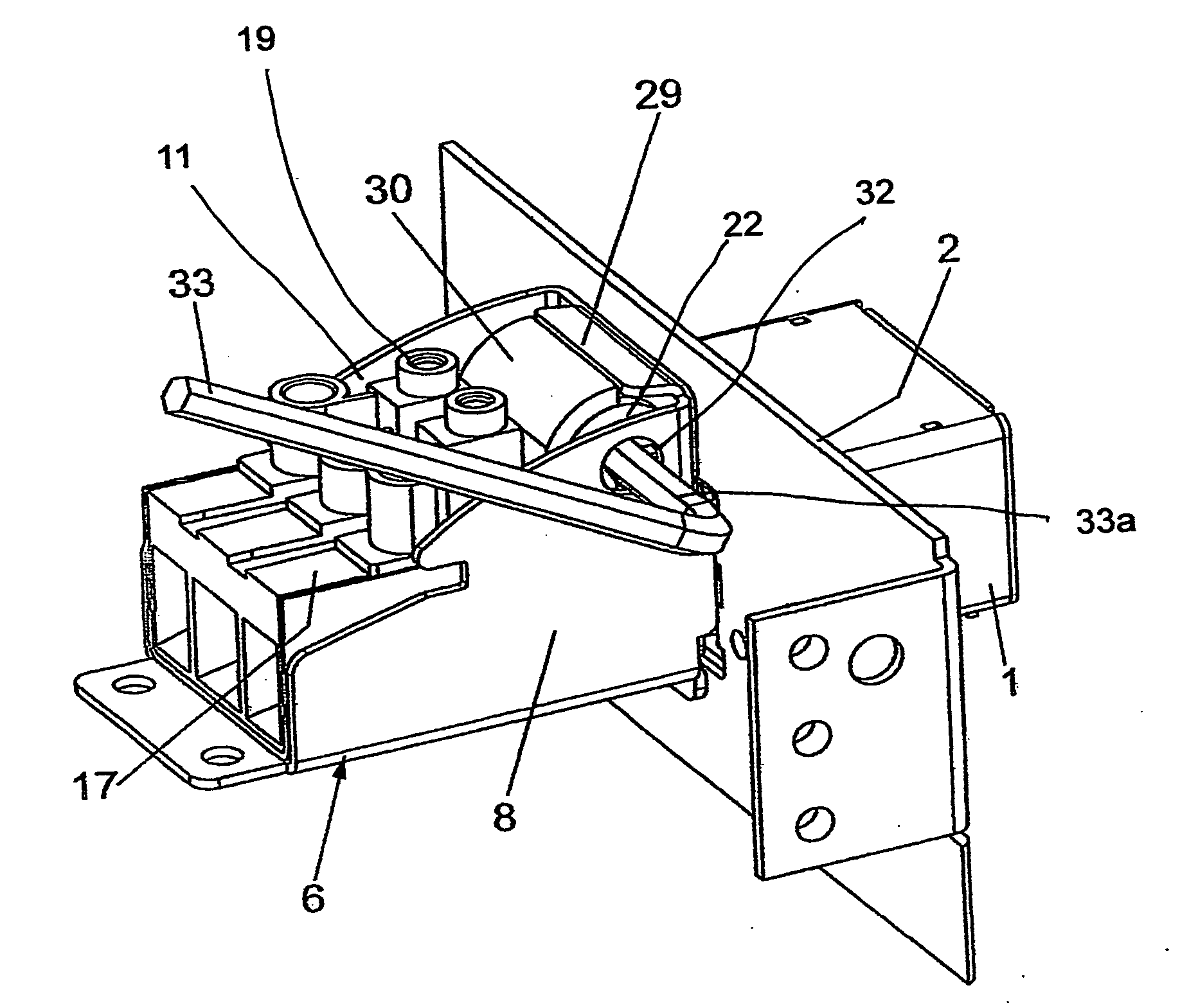
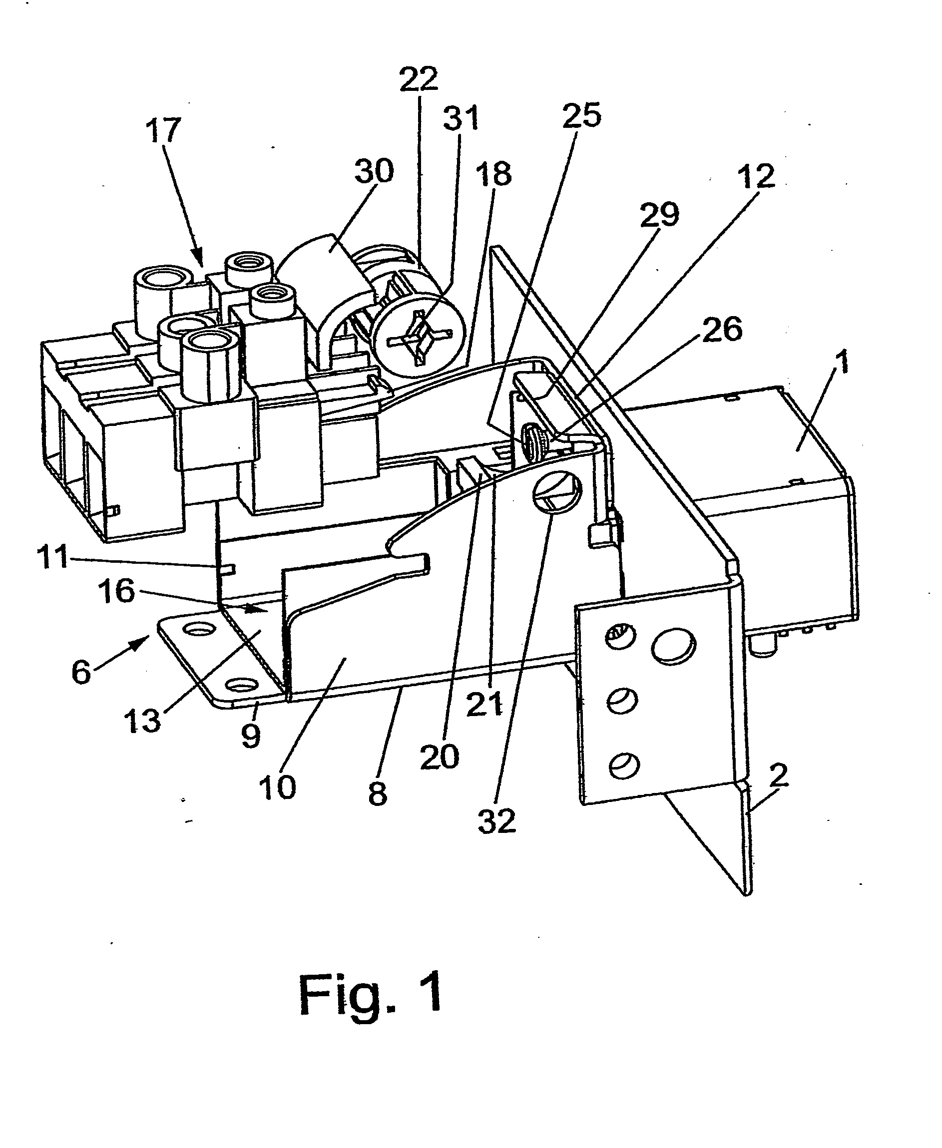
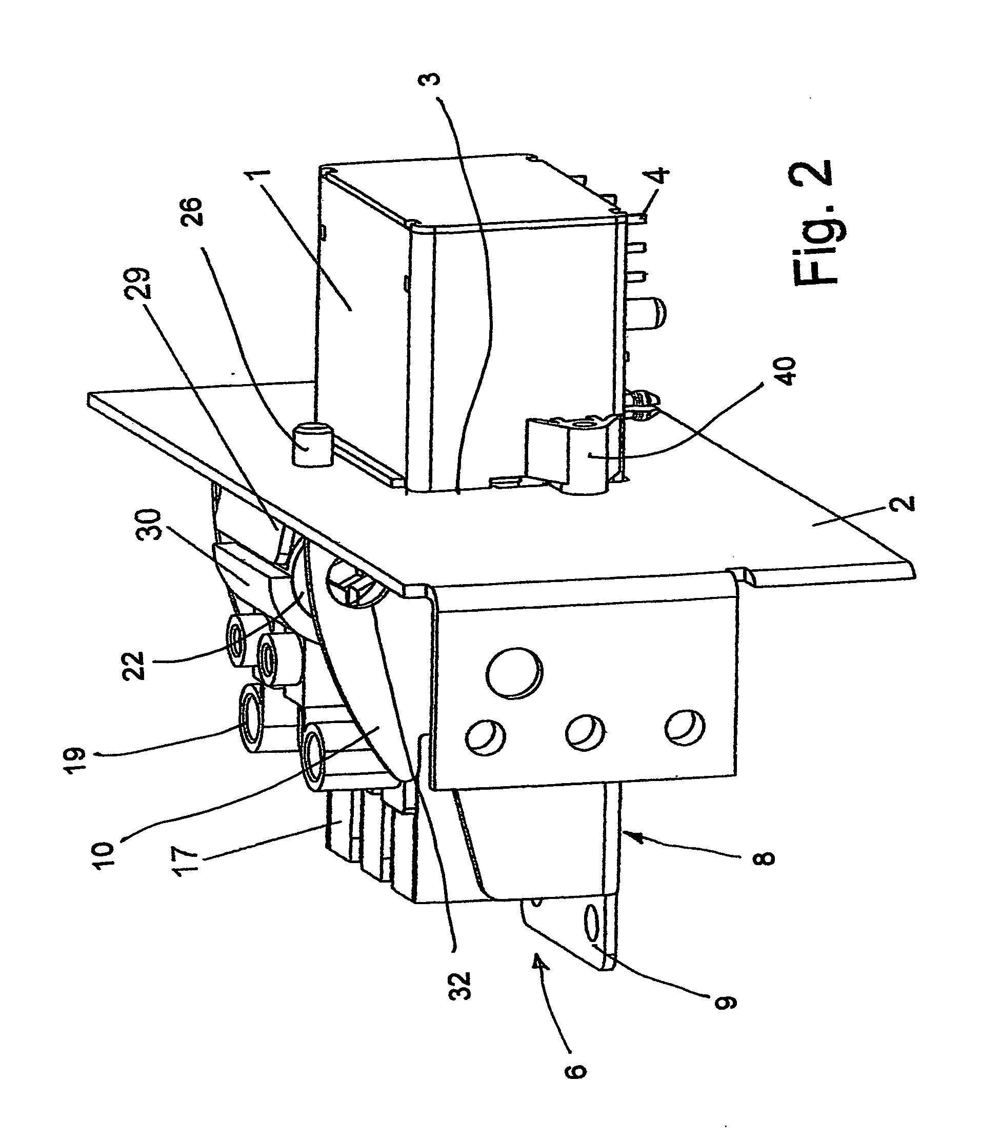
[0022]Referring first more particularly to FIGS. 1 and 2, the connector apparatus of the present invention includes a plug assembly 6 that is adapted for electrical connection with a socket 1 that is mounted in an opening 3 contained in a mounting wall 2. As shown in FIG. 2, the socket 1 is fastened to the rear surface of the vertical mounting wall 2 by fastening means 40. As will be described in greater detail below, the socket means 6 is locked to the front side of the vertical mounting wall 2 by locking means including a stationary locking peg 26 that is secured to the mounting wall 2 above the wall opening 3, and a cylindrical locking cam 22 that is rotatably supported at one end of the plug means 6 for pivotal movement about an axis parallel with the mounting wall 2, and transverse to the collinear axis of the socket 1 and the plug means 6.
[0023]The plug means 6 includes a sheet-material housing 8 having a horizontal bottom wall 9, a pair of vertical side walls 10 and 11, and a...
PUM
 Abstract
Description
Claims
Application Information