
System and methods for reduction of unwanted electronic correspondence

a technology of electronic correspondence and system, applied in the field of electronic correspondence, can solve problems such as large amount of unsolicited and illegitimate e-mail, problems for users of such correspondence, and abuse of users of e-mail and other electronic corresponden

Inactive Publication Date: 2008-07-10
MITCHELL TECH
View PDF16 Cites 14 Cited by
  • Summary
  • Abstract
  • Description
  • Claims
  • Application Information

AI Technical Summary

Benefits of technology

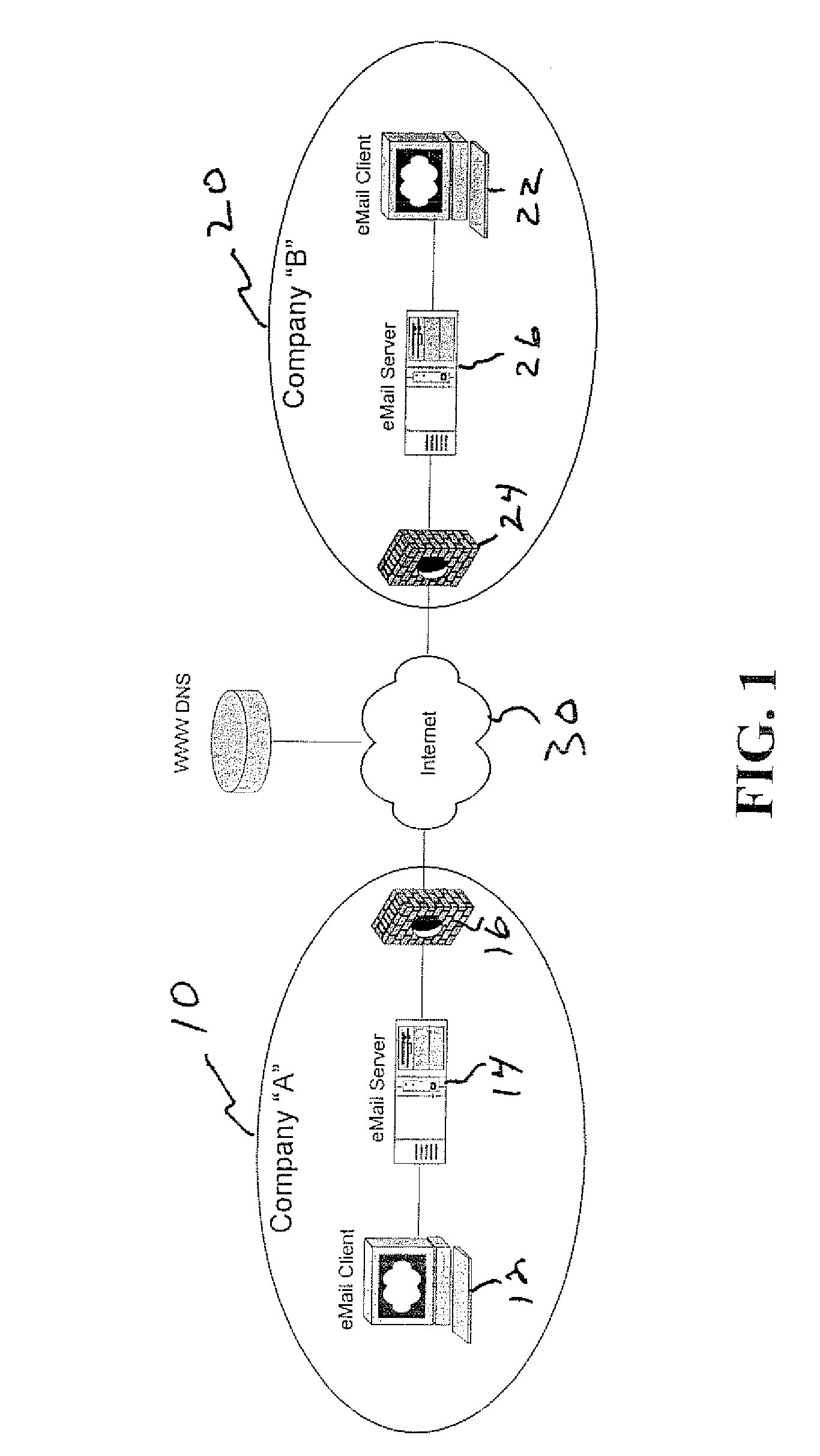
[0012]FIG. 1 is a schematic diagram showing a conventional system for sending and receiving electronic correspondence.

Problems solved by technology

However, the very advantages of e-mail and similar electronic correspondence have also caused a problem for users of such correspondence.
Specifically, users of e-mail and other electronic correspondence are being abused by what are commonly referred to as “spammers.” Such spammers send a large amount of unsolicited and illegitimate e-mail at virtually no cost to the sender.
However, the recipient of such messages has increased costs associated with the necessary memory required to save unsolicited e-mails, the time required by users to filter through the unwanted e-mails, and the general annoyance associated with spam.
However, such solutions are becoming more and more complex and expensive to implement as spammers become more resourceful and knowledgeable about their craft.
Moreover, as recipients are required to do additional filtering and place additional restrictions on their e-mail servers, and the like, the amount of legitimate correspondence being lost has increased.

Method used


Image

  • System and methods for reduction of unwanted electronic correspondence
  • System and methods for reduction of unwanted electronic correspondence
  • System and methods for reduction of unwanted electronic correspondence

Examples


Embodiment Construction

[0018]The present invention will be described with reference to the figures.

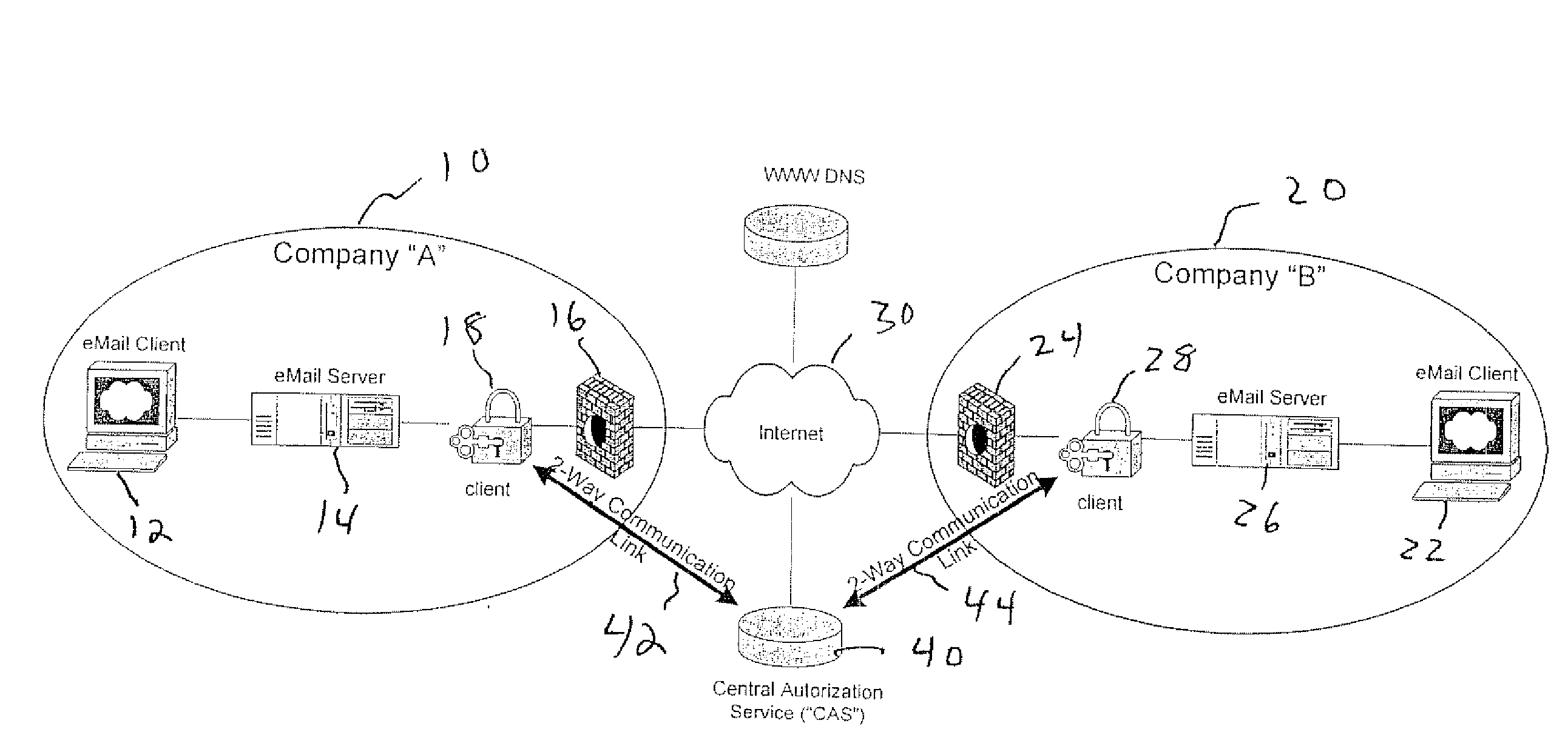
[0019]FIG. 1 illustrates a conventional configuration for implementing electronic correspondence between two entities. As illustrated therein, a plurality of entities 10, 20 (two are illustrated in FIG. 1) are connected by the Internet 30. Correspondence is sent by a sender 12 over the Internet 30 for receipt by a recipient 22. Upon receipt, the correspondence is first routed through a firewall 24, then is received in an e-mail or electronic correspondence server 26, which further routes the correspondence to an e-mail client 22 or user interface for viewing by the user. Conversely, when e-mail is to be sent from the e-mail client 22, an IP address is obtained and the message is sent out through the firewall 24 to the respective companies e-mail server 14 which is then available for ultimate delivery when the recipient connects via their e-mail client. Prior to reception of the e-mail, the e-mail server pref...


PUM


Abstract

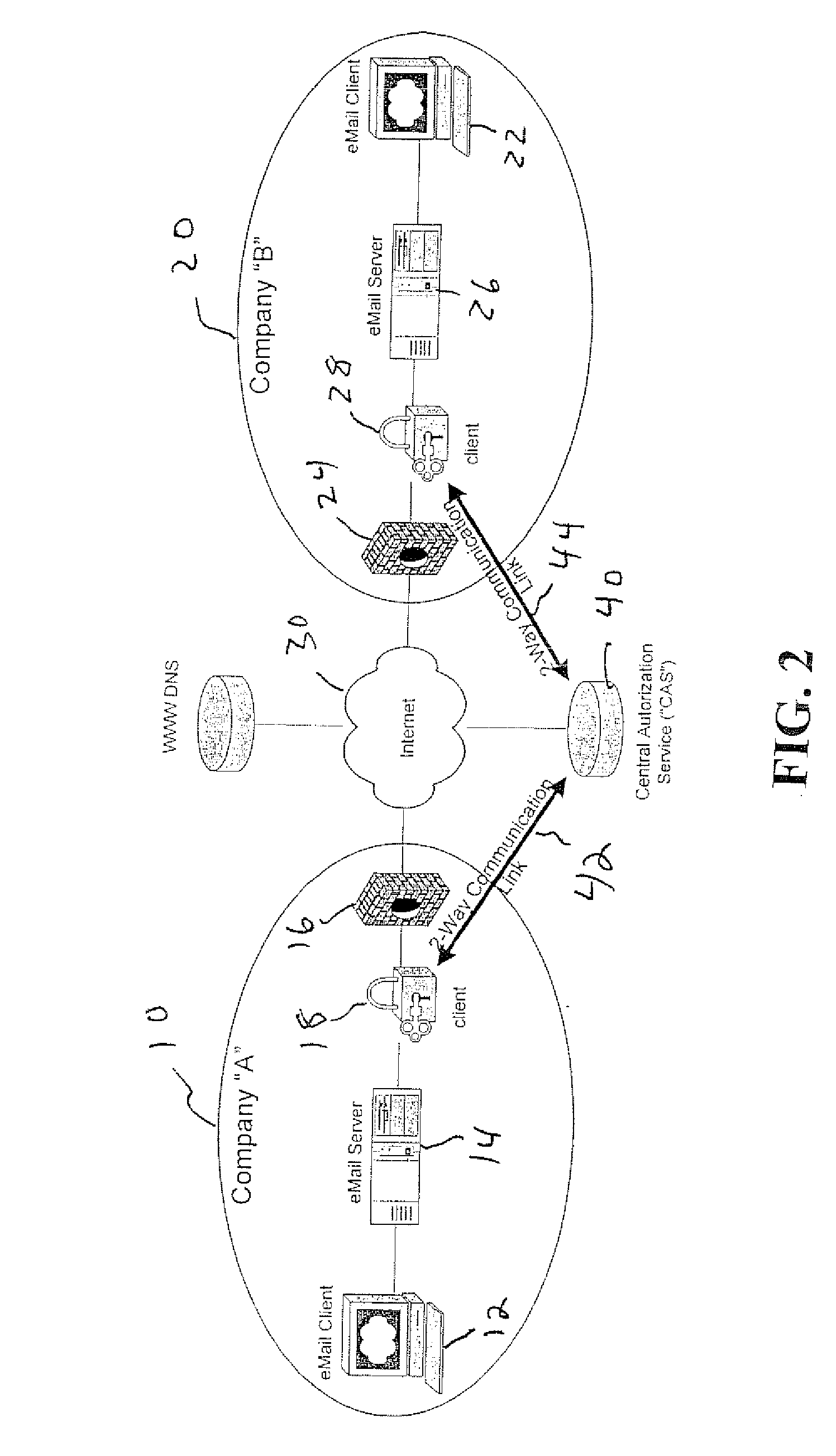
A system for authenticating electronic correspondence includes a sender, a recipient, and a central authorization service. The sender includes a correspondence client at which electronic correspondence is composed, a correspondence server for routing proposed correspondence, and a sender client. The recipient includes a correspondence client at which electronic correspondence is viewed, a correspondence server that delivers the correspondence to the correspondence client, and a recipient client. The central authorization service has a two-way communication link to each of the sender client and the recipient client. The sender client is configured to determine whether composed correspondence to be sent originates from at least one of an authorized server and an authorized domain before sending the correspondence and informs the central authorization service if a determination is made if the correspondence does not originate from an authorized server or an authorized domain. The recipient client determines the authenticity of received correspondence and only upon a determination of authenticity forwards the message to the correspondence server for routing to the recipient client.

Description

BACKGROUND OF THE INVENTION[0001]1. Field of the Invention[0002]The present invention relates generally to the field of electronic correspondence. More specifically, the present invention relates to a system for controlling the transmission and reception of electronic correspondence to substantially reduce the amount of unwanted correspondence.[0003]2. Brief Description of the Related Art[0004]Electronic mail has become a primary means of communication for a large number of organizations, businesses, and individuals. Electronic mail is particularly popular for its simplicity, efficiency, and its virtual non-existant cost.[0005]However, the very advantages of e-mail and similar electronic correspondence have also caused a problem for users of such correspondence. Specifically, users of e-mail and other electronic correspondence are being abused by what are commonly referred to as “spammers.” Such spammers send a large amount of unsolicited and illegitimate e-mail at virtually no cost...

Claims


Application Information

Patent Timeline
Patent Type & Authority Applications(United States)
IPC IPC(8): G06F7/04
CPCH04L12/585H04L51/12H04L9/321H04L63/166H04L63/083H04L51/212
Inventor RUECKWALD, MARK C.
Owner MITCHELL TECH
Learn More