Machine tool

Inactive Publication Date: 2008-07-17
DMG MORI SEIKI CO LTD
View PDF11 Cites 25 Cited by
  • Summary
  • Abstract
  • Description
  • Claims
  • Application Information

AI Technical Summary

Benefits of technology

[0009]The present invention has been made in view of the above-described problems, and an object thereof is to prov

Problems solved by technology

Therefore, for example, it is limited to observe the inside status of the machining area sufficiently even at the non-machining time in which a spindle has no workpiece attached thereto.
However, in the case of the structur

Method used


Image

  • Machine tool
  • Machine tool
  • Machine tool

Examples


Embodiment Construction

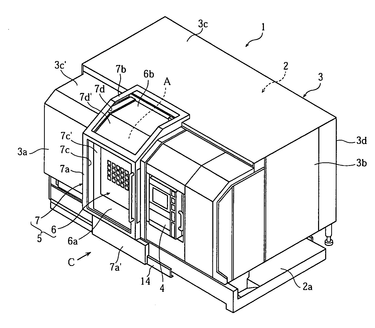
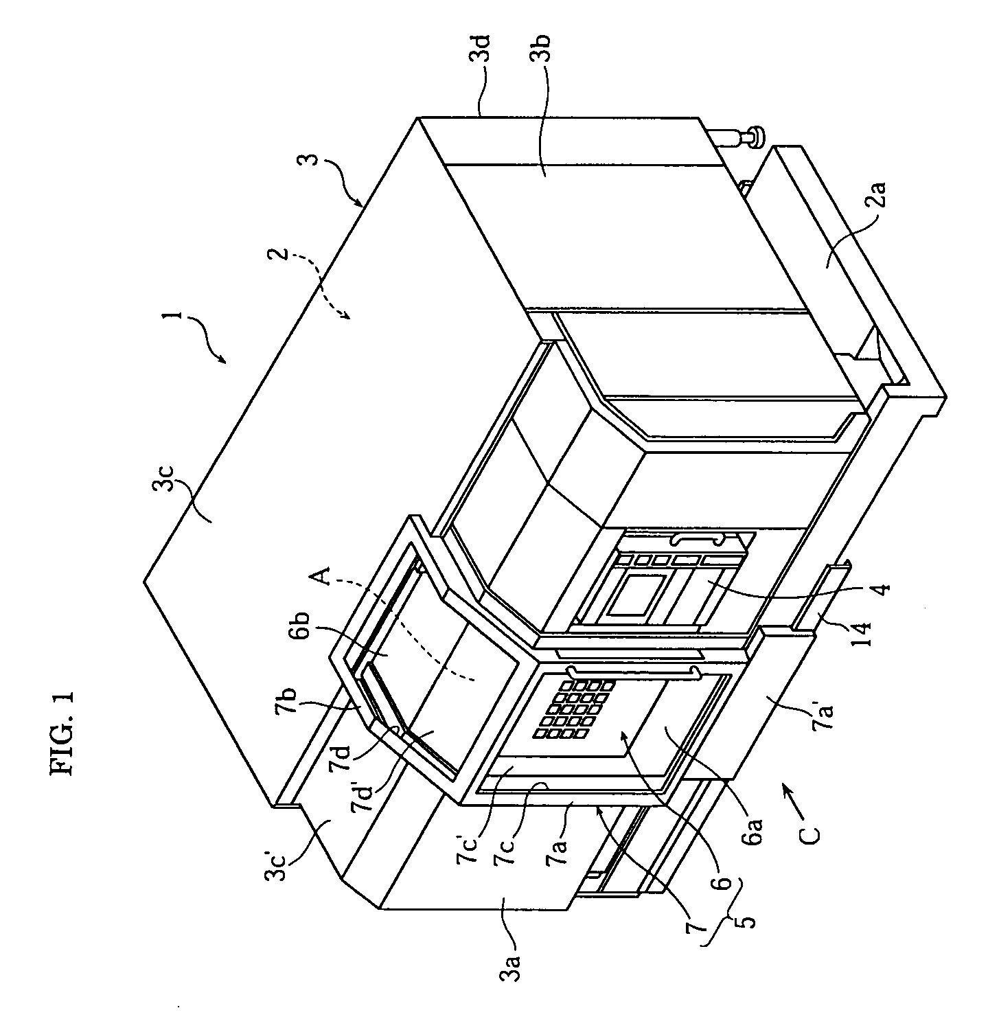
[0028]Hereinafter, an embodiment of the present invention will be described with reference to the attached drawings. FIG. 1 to FIG. 8 are views to illustrate a machine tool according to a first embodiment of the present invention. Note that, in the present embodiment, front, rear, right and left are the states when viewed from a machine front C, meaning a near side, a distant side, a right side and a left side, respectively.

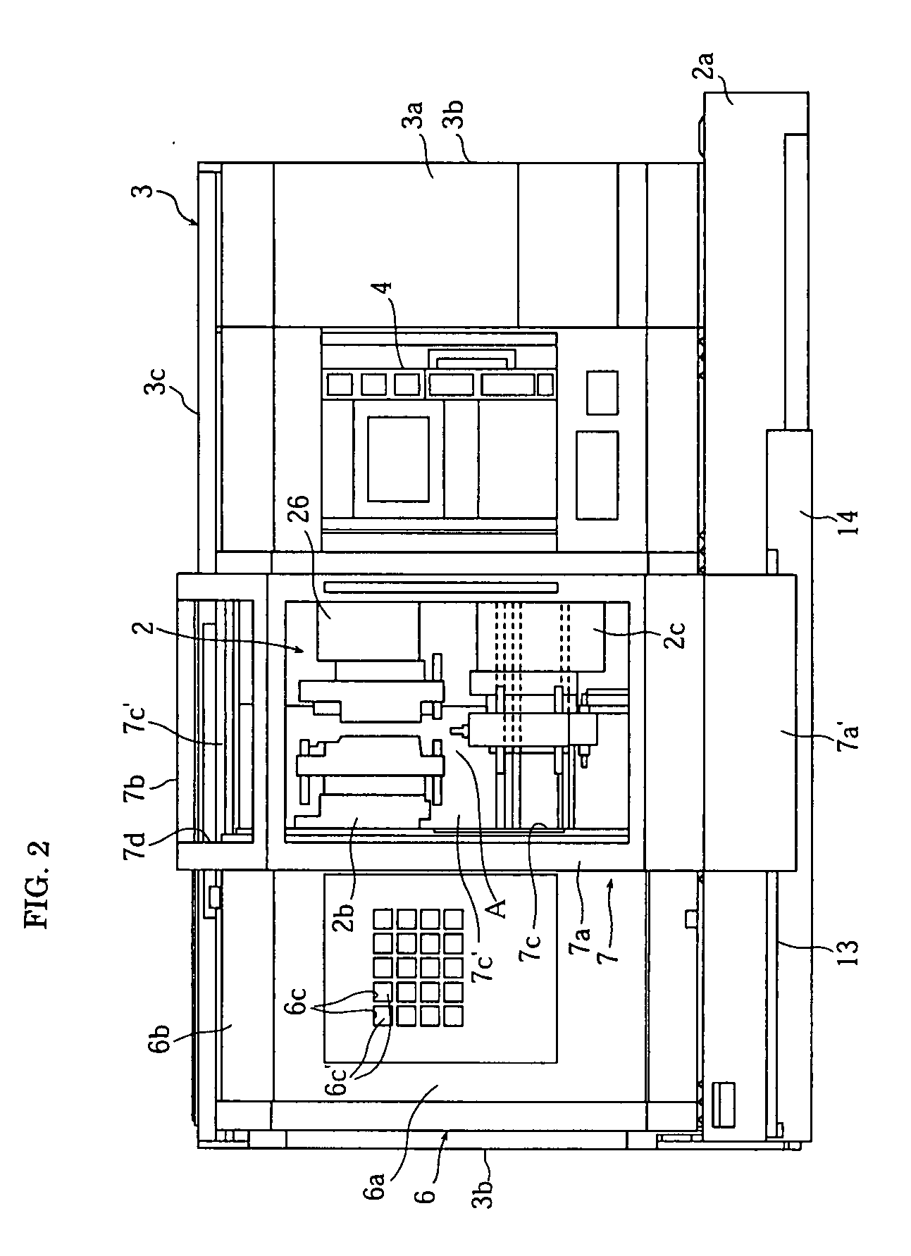
[0029]In these drawings, a numerical reference “1” denotes a lathe (machine tool) including a machine body 2 to machine a workpiece and a machine body cover 3 surrounding the periphery of the machine body 2. At almost the center in the right and left direction of the machine body 2, a machining area “A” to machine the workpiece is formed by a spindle (not shown) disposed on a bed 2a and a plurality of tool posts 2b, 2c.

[0030]The machine body cover 3 includes a front cover portion 3a, right and left side face cover portions 3b, 3b, a top face cover portion 3c and...


PUM

PropertyMeasurementUnit
Areaaaaaaaaaaa

Abstract

A machine tool capable of eliminating a laborious attachment/detachment work of a cover member is provided. The machine tool includes a door device 5 having a first door 6 to cover a machining-area opening 3e when machining a workpiece and a second door 7 to cover the machining-area opening 3e when not machining the workpiece and formed to be visible an inside thereof, in which the first door 6 and the second door 7 are arranged in a movable manner between a position-in-use covering the machining-area opening 3e and a position when opened opening the machining-area opening 3e.

Description

BACKGROUND OF THE INVENTION[0001]1. Field of the Invention[0002]The present invention relates to a machine tool including a machine body machining a workpiece, a machine body cover covering a periphery of the machine body, and a door device capable of opening / closing a machining-area opening formed in the machine body cover.[0003]2. Description of the Related Art[0004]In machine tools such as a lathe, a structure, in which the periphery of a machine body is surrounded by a machine body cover provided with a machining-area opening a machining area to be machined to outside and the machining-area opening is covered by a door in an openable / closable manner, is adopted.[0005]It is designed to prevent the workpiece from jumping to outside by covering the machining-area opening by the door, even when the workpiece is disengaged from a chuck in the course of the machining. In conventional machine tools, in general, a window is provided in the above-described door so that the inside status ...

Claims


Application Information

Patent Timeline
IPC IPC(8): B23B25/04B23Q11/08
CPCY10T409/30392Y10T74/2198Y10T82/2585Y10T82/2566B23Q11/0891Y10T82/2572
Inventor NISHI, SYUICHISAKAI, SHIGETSUGUYAMANE, MASAHIRO
Owner DMG MORI SEIKI CO LTD
Why Eureka
Try Eureka