Machine tool

a technology of machine tools and covers, applied in the field of machine tools, can solve the problems of limited observation of the inside status of the machining area, etc., and achieve the effect of reducing the laborious attaching/detaching work of the cover member

Inactive Publication Date: 2013-12-10
DMG MORI CO LTD
View PDF21 Cites 6 Cited by
  • Summary
  • Abstract
  • Description
  • Claims
  • Application Information

AI Technical Summary

Benefits of technology

[0010]The present invention has been made in view of the above-described problems, and an object thereof is to provide a machine tool capable of eliminating a laborious attaching / detaching work of a cover member as described above.
[0012]In the present invention, two doors, namely the first door to cover the machining-area opening when machining the workpiece and the second door to cover the machining-area opening when not machining the workpiece, are arranged in a movable manner between the position used to cover the machining-area opening and the position used to open the machining-area opening to outside, so that the machining-area opening can be covered as well as opened to outside with a necessary door by a simple operation of moving either or both of the first door or / and the second door.
[0013]Specifically, for example, when machining, even if the workpiece is disengaged to jump out, it is possible to prevent the workpiece from jumping to outside by covering the machining-area opening with the first door. Further, when rotating the spindle without attaching the workpiece thereto, it is possible to observe the inside by covering the machining-area opening with the second door. Furthermore, when exchanging the workpiece and the like, by moving both the doors to the positions for opening the machining-area opening, it is possible to exchange the workpiece or a tool, or to maintain the machine easily and surely. Note that, even when machining the workpiece, the machining is performed, for example at a low-level speed not possibility causing the workpiece to jump to outside, it is possible to observe the machining state by covering the machining-area opening with the second door.
[0014]As described above, compared with the conventional structure in which the separate cover member is attached to the machining-area opening in an attachable / detachable manner, the workability of the opening / closing work of the machining-area opening can be improved highly.
[0018]Further, since the second door is disposed outside the first door, the first door and the second door can be disposed and moved without interfering each other, so that the above-described workability can be improved further. Specifically, for example, when both the doors are disposed to form the same plane, both the doors are restricted in view of a position to be disposed and a moving direction, for example, when the first door is disposed on the left side of the machining-area opening in a movable manner, the second door is requisitely disposed on the right side thereof in the movable manner.

Problems solved by technology

Therefore, for example, it is limited to observe the inside status of the machining area sufficiently even at the non-machining time in which a spindle has no workpiece attached thereto.
However, in the case of the structure where the cover member is attached to the machining-area opening, the attaching / detaching work of the cover member is laborious and a space to dispose the detached cover member is additionally required, leaving problems.

Method used


Image

  • Machine tool
  • Machine tool
  • Machine tool

Examples


Embodiment Construction

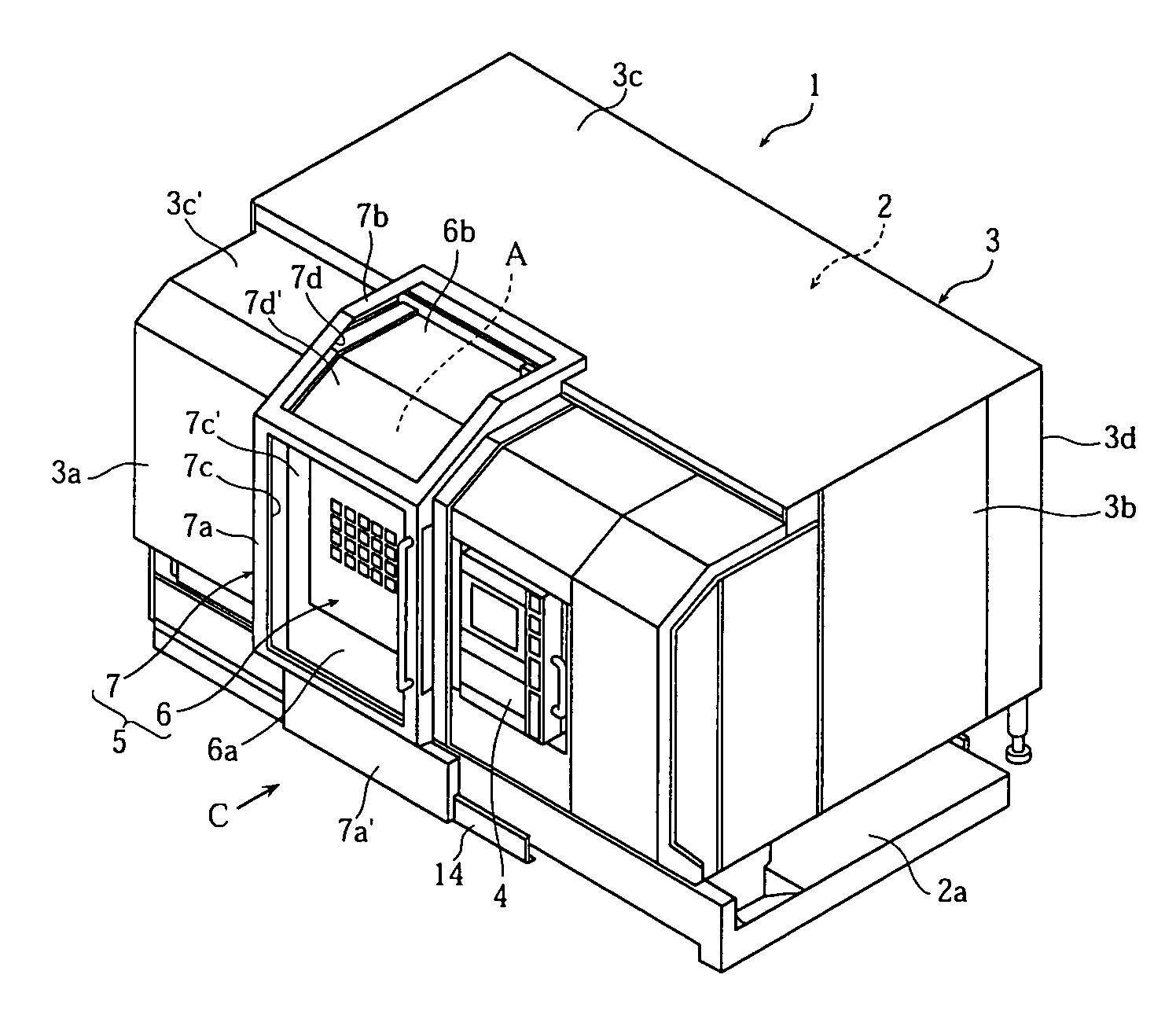
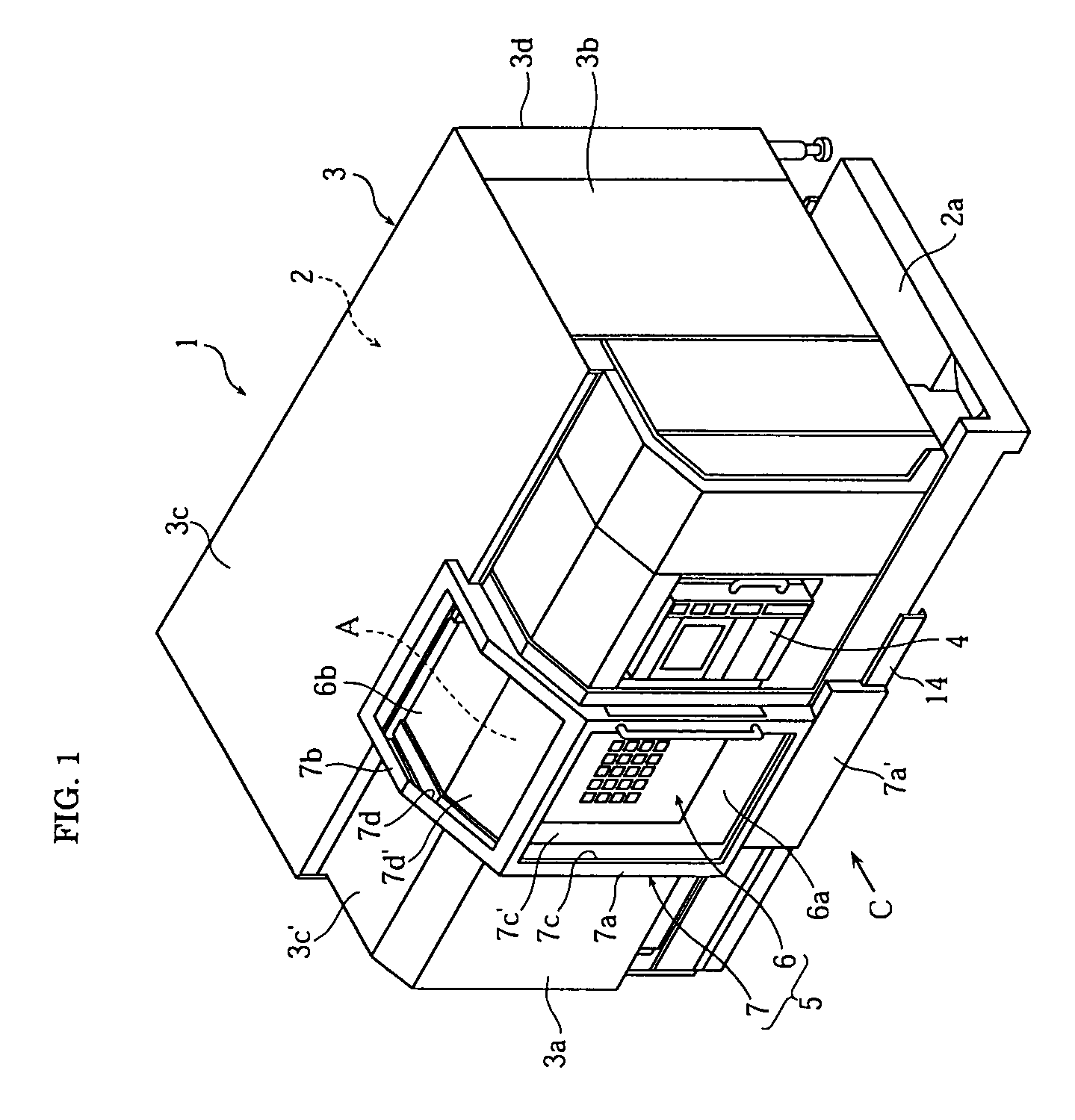
[0029]Hereinafter, an embodiment of the present invention will be described with reference to the attached drawings. FIG. 1 to FIG. 8 are views to illustrate a machine tool according to a first embodiment of the present invention. Note that, in the present embodiment, front, rear, right and left are the states when viewed from a machine front C, meaning a near side, a distant side, a right side and a left side, respectively.

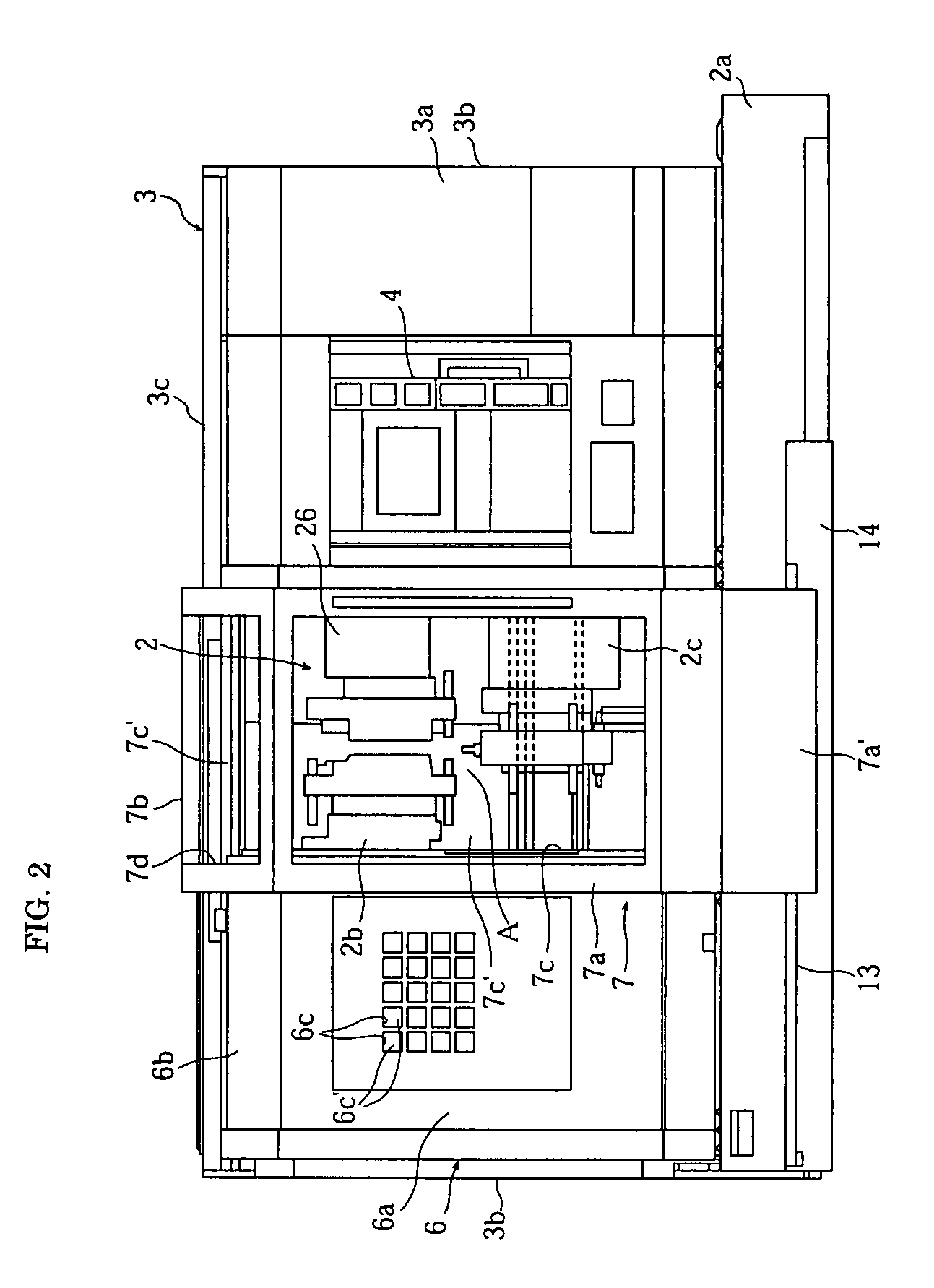
[0030]In these drawings, a numerical reference “1” denotes a lathe (machine tool) including a machine body 2 to machine a workpiece and a machine body cover 3 surrounding the periphery of the machine body 2. At almost the center in the right and left direction of the machine body 2, a machining area “A” to machine the workpiece is formed by a spindle (not shown) disposed on a bed 2a and a plurality of tool posts 2b, 2c.

[0031]The machine body cover 3 includes a front cover portion 3a, right and left side face cover portions 3b, 3b, a top face cover portion 3c and...


PUM

PropertyMeasurementUnit
machining areaaaaaaaaaaa
areaaaaaaaaaaa
sizeaaaaaaaaaa

Abstract

A machine tool capable of eliminating a laborious attachment / detachment work of a cover member is provided. The machine tool includes a door device 5 having a first door 6 to cover a machining-area opening 3e when machining a workpiece and a second door 7 to cover the machining-area opening 3e when not machining the workpiece and formed to be visible an inside thereof, in which the first door 6 and the second door 7 are arranged in a movable manner between a position-in-use covering the machining-area opening 3e and a position when opened opening the machining-area opening 3e.

Description

BACKGROUND OF THE INVENTION[0001]1. Field of the Invention[0002]The present invention relates to a machine tool including a machine body machining a workpiece, a machine body cover covering a periphery of the machine body, and a door device capable of opening / closing a machining-area opening formed in the machine body cover.[0003]2. Description of the Related Art[0004]In machine tools such as a lathe, a structure, in which the periphery of a machine body is surrounded by a machine body cover provided with a machining-area opening a machining area to be machined to outside and the machining-area opening is covered by a door in an openable / closable manner, is adopted.[0005]It is designed to prevent the workpiece from jumping to outside by covering the machining-area opening by the door, even when the workpiece is disengaged from a chuck in the course of the machining. In conventional machine tools, in general, a window is provided in the above-described door so that the inside status ...

Claims


Application Information

Patent Timeline
Patent Type & Authority Patents(United States)
IPC IPC(8): B23Q11/08
CPCB23Q11/0891Y10T74/2198Y10T409/30392Y10T82/2585Y10T82/2572Y10T82/2566
Inventor NISHI, SYUICHISAKAI, SHIGETSUGUYAMANE, MASAHIRO
Owner DMG MORI CO LTD
Why Eureka
Try Eureka