Motor magnet fixing device

a technology for fixing devices and motor magnets, which is applied in the direction of dynamo-electric machines, electrical equipment, and magnetic circuit shapes/forms/construction, etc. it can solve the problems of magnet damage, magnet weakened, and motor damage, and achieve stable magnet magnetic polarity, shorten production time, and facilitate assembly

Inactive Publication Date: 2008-07-17
AIR COOL INDAL
View PDF8 Cites 17 Cited by
  • Summary
  • Abstract
  • Description
  • Claims
  • Application Information

AI Technical Summary

Benefits of technology

[0007]The objective of this invention is to offer a motor magnet fixing device composed of at least two press rings, a plurality of magnets preset in number and plural locking members. At least one of the two press rings has its annular surface disposed thereon with a plurality of projecting members spaced apart equidistantly. Each projecting member is axially bored with a fixing hole and has its opposite sides respectively formed with an en gage recess. The magnets are firmly sandwiched between the two press rings and respectively engaged between the adjacent projecting members of the two press rings. Each magnet has its opposite sides respectively formed with an engage projection to be respectively engaged in the adjacent engage notches of the projecting members of the two press rings. The locking members are respectively inserted in the fixing holes of the projecting members of the two press rings to combine the two press rings together, letting the magnets firmly clamped between the two press rings. Thus, each magnet has its opposite engage projections engaged and restrictedly positioned in the engage notches of the adjacent projecting members of the two press rings; therefore, the magnetic action of the magnets can evenly be distributed within the two press rings, able to stabilize the magnetic polarity of the magnets. In addition, the two press rings are made of plastic; therefore, when the locking members are respectively inserted in the fixing holes of the projecting members of the two press rings for combining the two press rings together and securing the magnets between the two press rings, the locking members can be quickly guided and inserted in the fixing holes. Additionally, since the locking members are separated from the magnets by parts of the plastic press rings, they will not be affected by the magnetic action of the magnets and hence can be easily assembled in the two press rings, possible to cut short the time required in production and elevate market competitive capability.

Problems solved by technology

However, the adhesives may become weakened in its viscosity after used for a long period of time, rendering the magnets likely to fall off and causing damage to the motor.
In addition, when glued on the inner wall of the motor housing, the magnets, due to mutual attraction and repelling of magnetic polarity, are likely to move bias and hard to be precisely fixed in position.
As a result, it is inconvenient to assemble the magnets and impossible to separate and arrange the magnets equidistantly with precise intervals, thus failing to make magnetic action of the magnets distributed evenly and unable let the motor operate stably.
However, due to the attracting and repelling action of magnetic polarity, when the magnets 11 are assembled on the opposite inner walls of the motor housing 10 by means of the two positioning rings 12, it will always cause trouble in operation, and when the bolts 13 are respectively inserted through the insert hole 122 and the gaps between two magnets 11 and locked with the nut 131, the bolts 13 will be actuated to sway bias by the magnetic action of the magnets 11 and hard to be fixed in position quickly and precisely, resulting in difficulty and inconvenience in assembly and operation.

Method used


Image

  • Motor magnet fixing device
  • Motor magnet fixing device
  • Motor magnet fixing device

Examples


Embodiment Construction

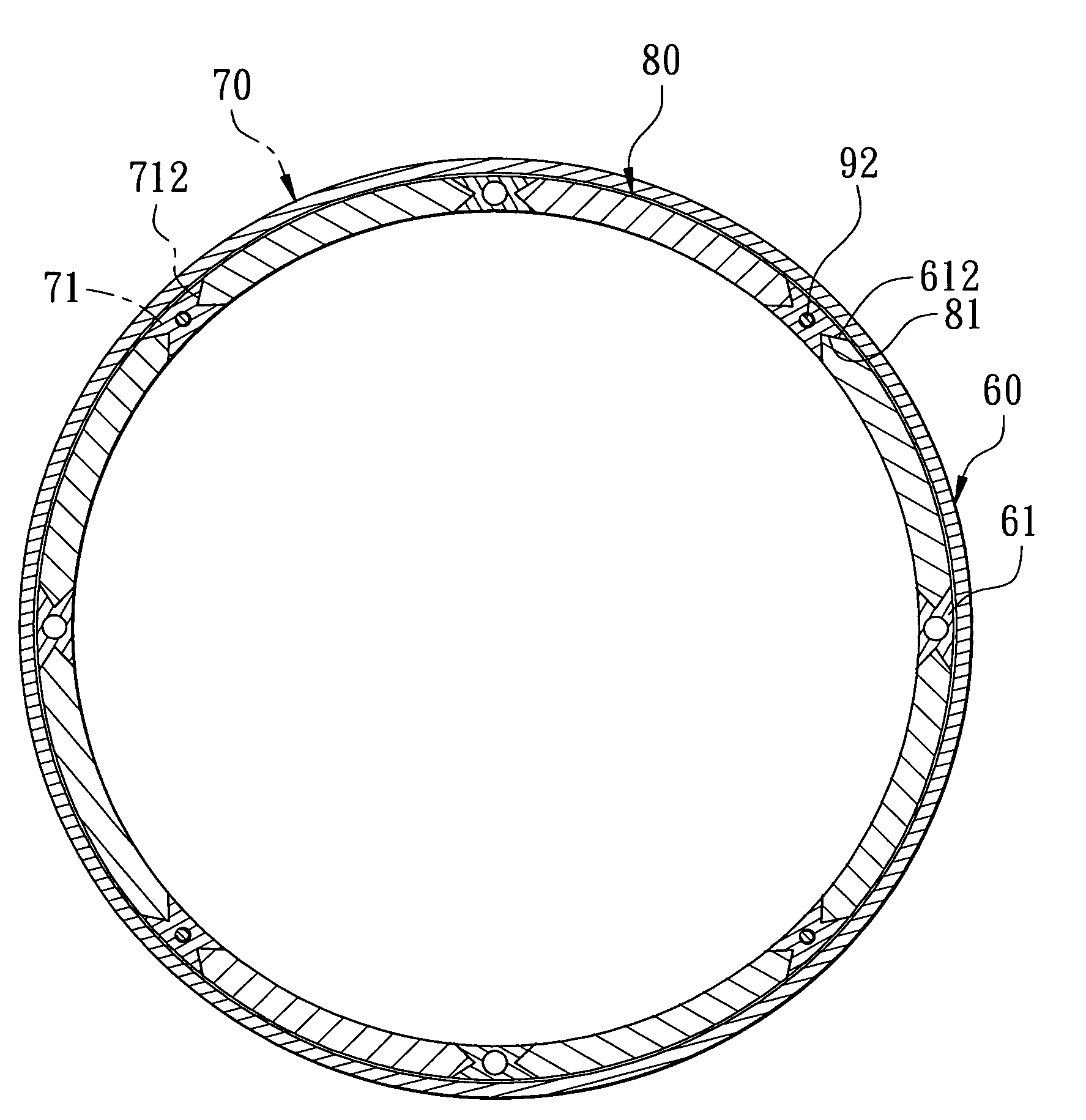
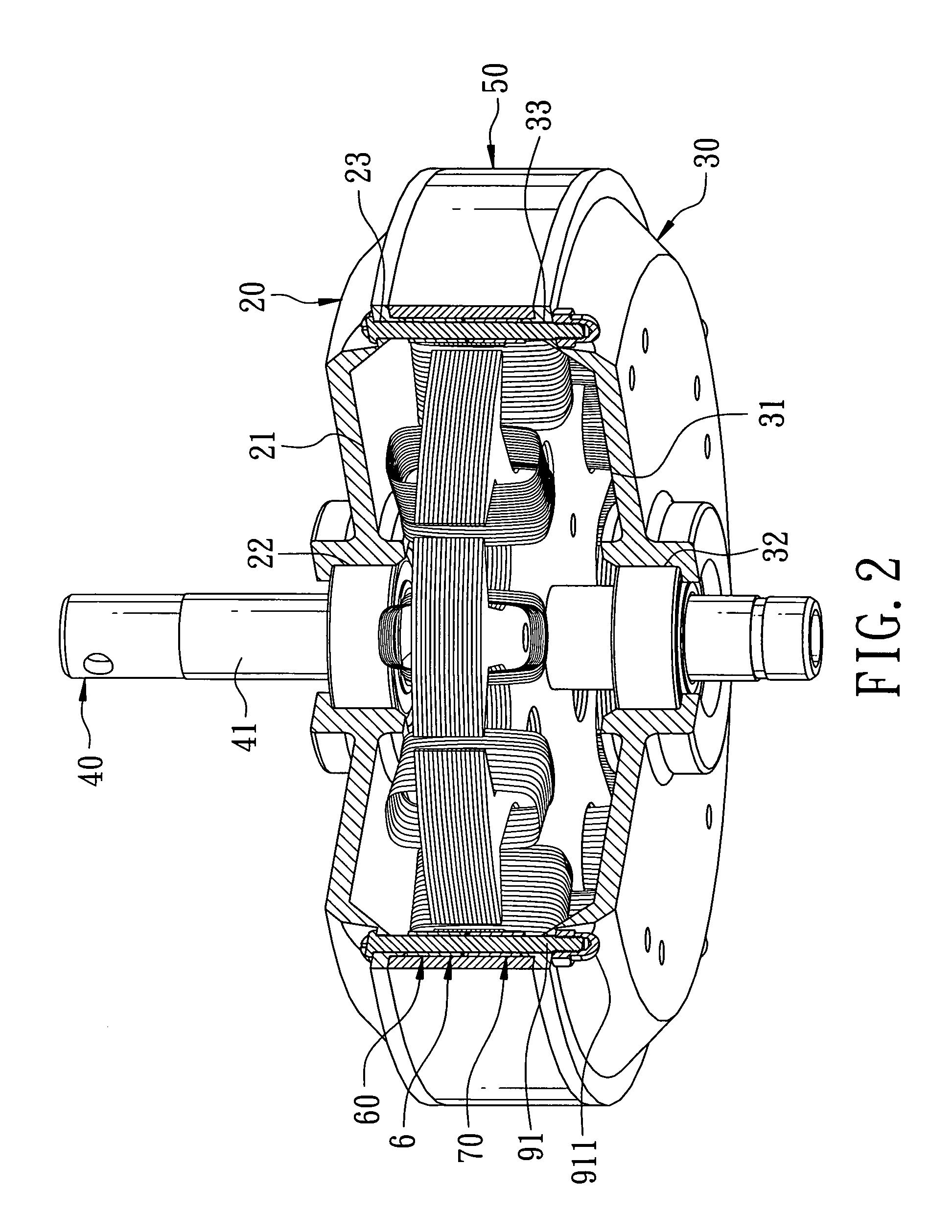
[0016]A first preferred embodiment of a motor magnet fixing device in the present invention, as shown in FIGS. 2 and 3, includes an upper motor housing 20, a lower motor housing 30, a rotor 40, an intermediate ring 50 and a magnet fixing device 6 combined together.

[0017]The upper motor housing 20 is shaped as a circular disc having one side provided with a combining member 21 and its central portion bored with a combining hole 22 and also having its annular edge bored with a plurality of insert holes 23 spaced apart at a preset interval.

[0018]The lower motor housing 30 shaped as a circular disc corresponding with the upper motor housing 20 is provided with a combining member 31 at one side facing the upper motor housing 20 and bored in the center with a combining hole 32 aligned to the combining hole 22 of the upper motor housing 20. The lower motor housing 30 further has its annular edge bore-d with a plurality of insert holes 33 respectively aligned to the insert holes 23 of the u...


PUM


Abstract

A motor magnet fixing device includes two press rings, a plurality of magnets and locking members. A least one of the two press rings has its annular surface disposed with a plurality of projecting members spaced apart equidistantly. Each projecting member is axially bored with a fixing hole, having its opposite sides respectively formed with an engage recess. The magnets are clamped between the two press rings and respectively engaged between the adjacent projecting members of the two press rings. Each magnet has its opposite ends respectively formed with an engage projection to be engaged in the engage recesses of the projecting members of the press rings. The locking members are respectively inserted in the fixing holes of the projecting members of the press rings to combine the press rings together and fix the magnets between the press rings.

Description

BACKGROUND OF THE INVENTION[0001]1. Field of the Invention[0002]This invention relates to a motor magnet fixing device, particularly to one provided with two press rings and a plurality of locking members to have motor magnets clamped firmly between the two press rings, able to fix the motor magnets in position and facilitate its assembly.[0003]2. Description of the Prior Art[0004]Generally, a conventional motor magnet fixing device is provided with plural magnets preset in number to be equidistantly secured on the inner wall of a motor housing by means of adhesives, and a rotor installed in the interior of the motor housing to be actuated to rotate and produce electric force by change of the magnetic line of force and the magnetic field of the magnets. However, the adhesives may become weakened in its viscosity after used for a long period of time, rendering the magnets likely to fall off and causing damage to the motor. In addition, when glued on the inner wall of the motor housin...

Claims


Application Information

Patent Timeline
Patent Type & Authority Applications(United States)
IPC IPC(8): H02K21/12
CPCH02K1/2786H02K1/17H02K1/2791
Inventor YU, TANG YUNG
Owner AIR COOL INDAL
Why Eureka
Try Eureka