Multistage series circuit system

a series circuit and multi-stage technology, applied in the direction of battery overcharge protection, safety/protection circuit, emergency protective arrangements for limiting excess voltage/current, etc., to achieve the effect of simplifying the system and reducing the positive excess voltag

Inactive Publication Date: 2008-07-17
DENSO CORP
View PDF4 Cites 8 Cited by
  • Summary
  • Abstract
  • Description
  • Claims
  • Application Information

AI Technical Summary

Benefits of technology

[0018]According to a third aspect of the present disclosure, a multistage series circuit system includes: a plurality of DC power source, which are coupled in series with each other; a plurality of unit circuits, each of which is coupled in parallel with a corresponding DC power source; and a plurality of protection circuits for protecting each unit circuit and the whole system. Each protection circuit is coupled between a positive side terminal of a corresponding DC power supply and a minimum reference potential terminal of the plurality of DC power sources. Each protection circuit functions to reduce a positive excess voltage when the positive excess voltage is applied to the unit circuit. Each protection circuit functions to flow a current along with a voltage applying direction of a negative excess voltage when the negative excess voltage is applied to the unit circuit.
[0019]In the above system, the construction of the system is simplified. Further, each unit circuit is individually protected, and the whole system, i.e., the part of the whole unit circuits, is also protected.

Problems solved by technology

The inventor raises a problem about the multistage series circuit system.

Method used


Image

  • Multistage series circuit system
  • Multistage series circuit system
  • Multistage series circuit system

Examples


first embodiment

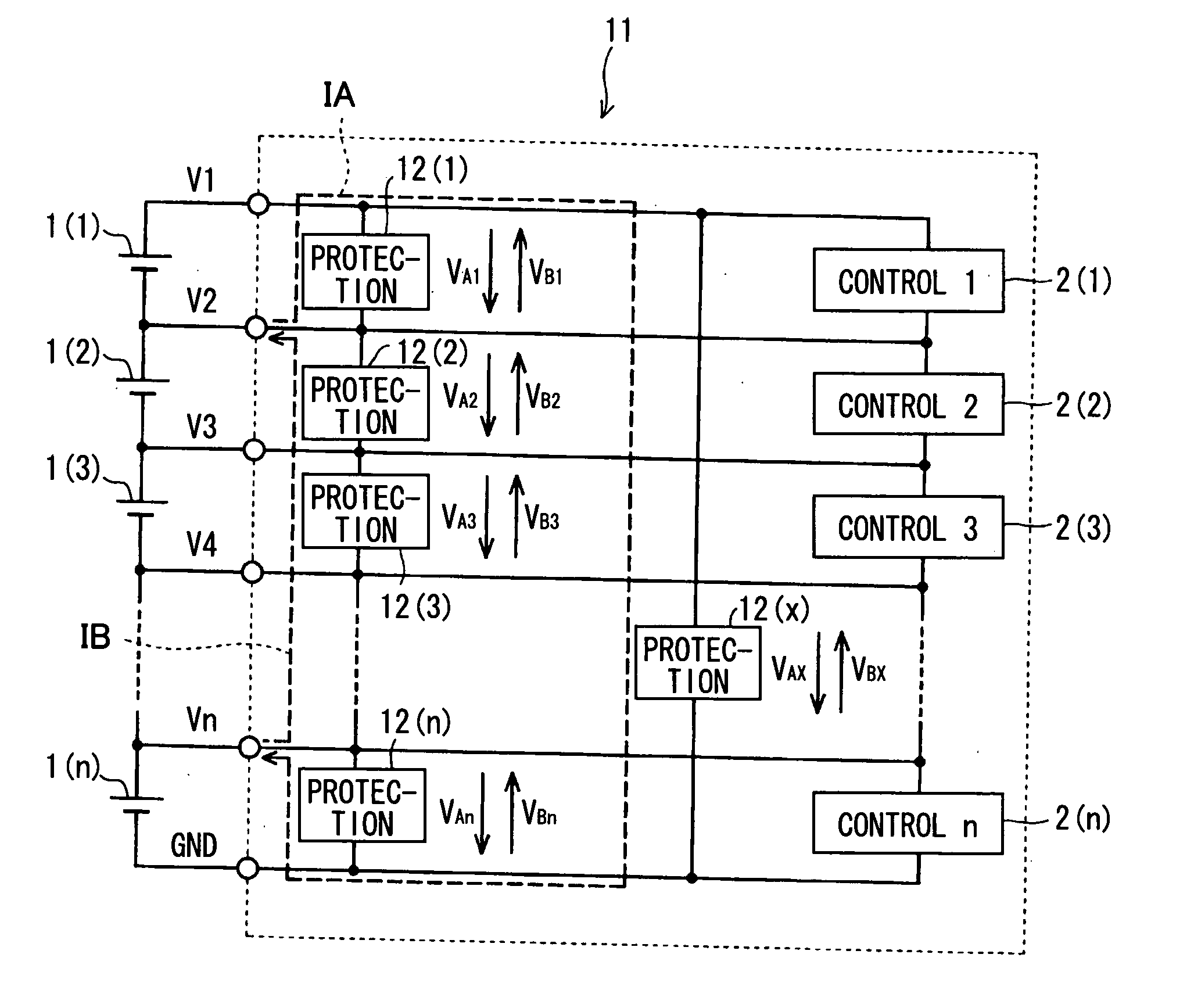
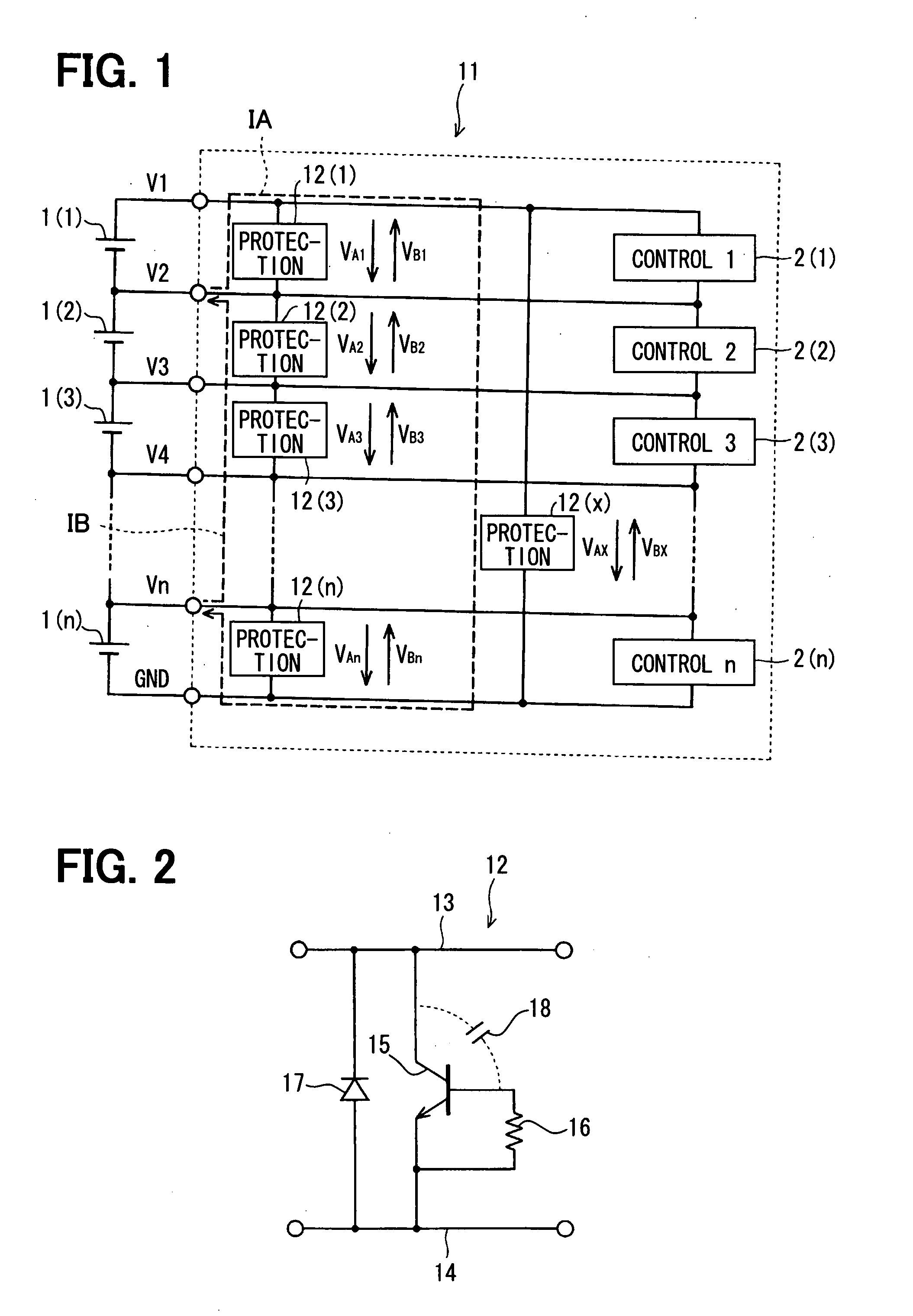
[0026]FIG. 1 shows a multistage series circuit system 11 having multiple DC power supplies 1(1)-1(n), multiple unit circuits 2(1)-2(n), i.e., multiple control circuits, and multiple protection circuits 12(1)-12(n). Here, VA1 to VAn represent positive surge clamp voltages, and VB1 to VBn represent negative surge clamp voltages. IA represents a loop for positive surge protection, and IB represents a loop (or a route) for negative surge protection. The system 11 further includes an additional protection circuit 12(x) as a whole circuit protection circuit, which is disposed between the first terminal V1 and the ground GND. Each protection circuit 12(1)-12(n) functions as an individual circuit protection circuit.

[0027]FIG. 2 shows one of the individual circuit protection circuits 12(1)-12(n) and the whole circuit protection circuit 12(x). The protection circuit 12 includes a NPN transistor 15, a resistor 16 and a diode 17. The NPN transistor 15 has a collector connecting to a high potent...

second embodiment

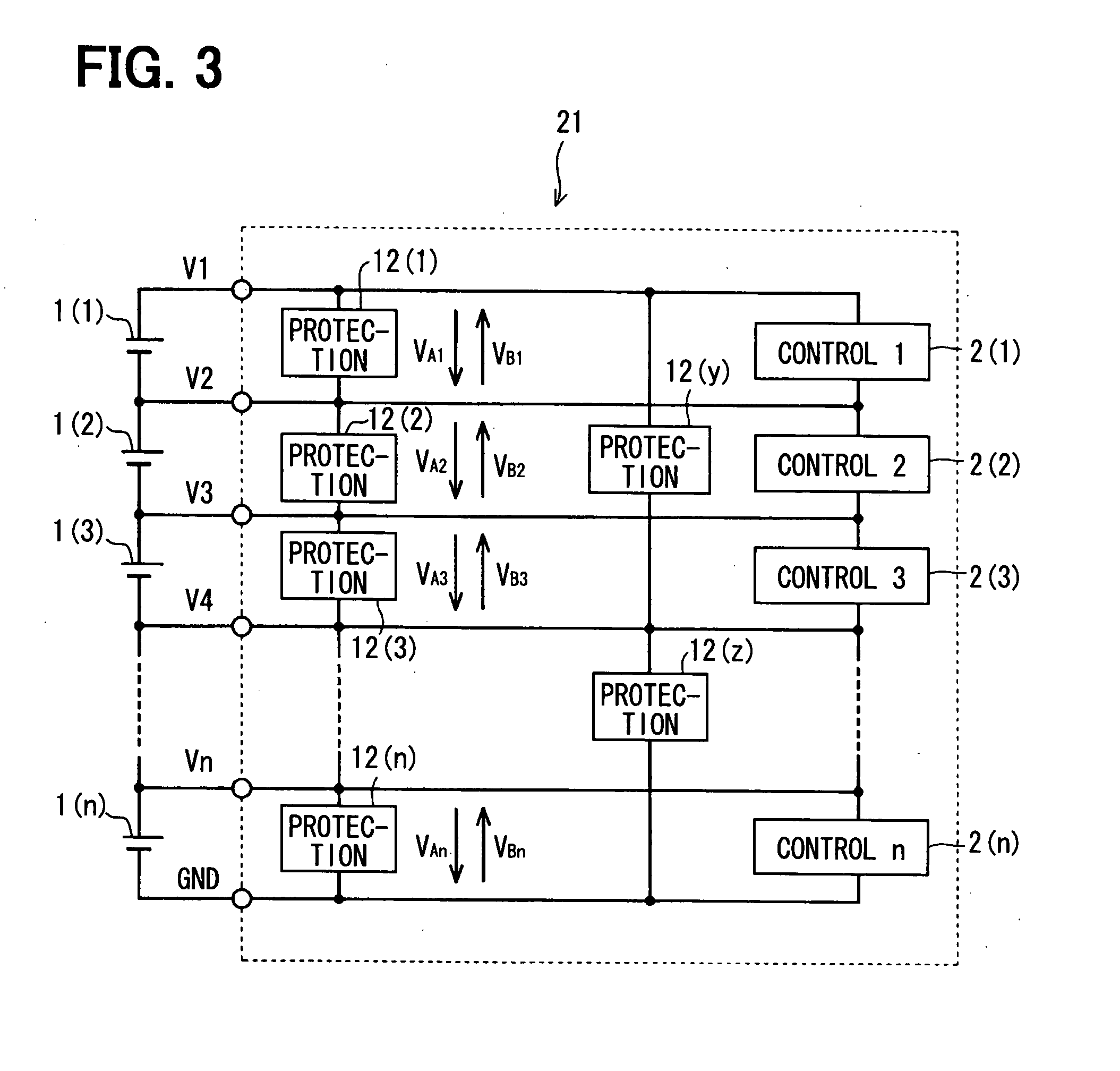
[0035]FIG. 3 shows a multistage series circuit system 21 according to a second embodiment of the present disclosure. The system 21 includes a pair of group protection circuits 12(y), 12(z). The first group protection circuit 12(y) is disposed between the first terminal V1 and the fourth terminal V4, and the second group protection circuit 12(z) is disposed between the fourth terminal V4 and the ground GND. Here, the control circuits 12(1)-12(3) provide a first series group, and the control circuits 12(4)-12(n) provide a second series group.

[0036]When a surge voltage is applied to one of the terminals V1-V4, the first group protection circuit 12(y) functions as a protection circuit in the first series group. When a surge voltage is applied to one of the terminals V4-GND, the second group protection circuit 12(z) functions as a protection circuit in the second series group. Further, when a surge voltage is applied to one of the terminals V1-V4 and another surge voltage is applied to o...

third embodiment

[0038]FIG. 4 shows a multistage series circuit system 22 according to a third embodiment of the present disclosure. In the system 22, a negative side terminal of each protection circuit 12(1)-12(n) is connected to a negative side terminal of the power source 1(n), i.e., the ground GND. Specifically, the protection circuit 12(1)-12(n) is not connected in parallel to the control circuit 2(1)-2(n).

[0039]When a positive surge voltage is applied between the first terminal V1 and the ground GND, the clamp voltage is defined as VA1, and when a negative surge voltage is applied between the first terminal V1 and the ground GND, the clamp voltage is defined as VB1. When the positive surge voltage is applied between two terminals other than the first terminal V1 and the ground GND, the clamp voltage is defined as VAx+VBx, and when the negative surge voltage is applied between two terminals other than the first terminal V1 and the ground GND, the clamp voltage is also defined as VAx+VBx. For ex...


PUM


Abstract

A multistage series circuit system includes: multiple DC power sources coupled in series with each other; multiple unit circuits coupled in parallel with a power source; multiple first protection circuits for protecting each unit circuit; and a second protection circuit for protecting the whole system. Each first protection circuit is coupled in parallel with the unit circuit. The second protection circuit is coupled in parallel with the whole system. Each protection circuit functions to reduce a positive excess voltage when the positive excess voltage is applied to the unit circuit or the whole system. Each protection circuit functions to flow a current along with a voltage applying direction of a negative excess voltage when the negative excess voltage is applied to the unit circuit or the whole system.

Description

CROSS REFERENCE TO RELATED APPLICATIONS[0001]This application is based on Japanese Patent Applications No. 2007-3369 filed on Jan. 11, 2007, and No. 2007-167595 filed on Jun. 26, 2007, the disclosures of which are incorporated herein by reference.FIELD OF THE INVENTION[0002]The present invention relates to a multistage series circuit system.BACKGROUND OF THE INVENTION[0003]A multistage series circuit system includes multiple DC power supplies and multiple unit circuits. The DC power supplies are coupled in series with each other. Each unit circuit is connected in parallel with a corresponding DC power supply.[0004]A lithium battery as a secondary battery (i.e., a rechargeable battery) generates a voltage about four volts. Multiple lithium batteries are connected in series with each other so that a desired voltage of a power source is obtained. It is necessary for the lithium battery to monitor a charging state and a discharging state of the battery and to control avoiding excess cha...

Claims


Application Information

Patent Timeline
Patent Type & Authority Applications(United States)
IPC IPC(8): H02H9/04
CPCH02J7/0026H02J7/0014H02J7/00308H02J7/00302H02J7/00306
Inventor OSAMURA, NOBUYOSHI
Owner DENSO CORP
Why Eureka
Try Eureka