Conductive component

Inactive Publication Date: 2008-07-17
KENDOO TECH
View PDF2 Cites 4 Cited by
  • Summary
  • Abstract
  • Description
  • Claims
  • Application Information

AI Technical Summary

Benefits of technology

[0015]The primary objective of the present invention is to provide a battery holder having a conductive component with improved current tolerance. The conductive component has a housing and a conductor. The housing is conductive and has a contact end, a distal end, a through hole and an inner surface. The through hole is formed through the contact end and the distal end. The conductor is mounted movably in the through hole of the housing and has a distal end, a proximal end, a conducting portion, a side wall and a recess. The proximal end of the conductor is held in the through hole of the housing. The conducting portion is formed on and protrudes out from the proximal end of the conductor and protrudes out from the contact end of the housing. The side wall corresponds to and abuts the inner surface of the housing. The recess is formed coaxially in the distal end of the conductor. Because the conductor has an increased surface to contact with the inner surface of the housing, the battery holder has an improved current tolerance.
[0016]Based on the structure of the battery holder as described, the conductor in accordance with the present invention has an added surface of the side wall in contact with the housing, whereby a high current transiently produced by a battery passes through the added outer surface and does not cause the spring of the battery holder in accordance with the present invention to melt. In consequence, the battery holder in accordance with the present invention has an improved transient current tolerance.

Problems solved by technology

Therefore, the battery cannot be easily removed from the electric vehicle, causing difficulty in maintaining the electric vehicle.
However, when the battery transiently produces a high current, the high current may cause the spring (33) of the conventional battery holder to melt.

Method used


Image

  • Conductive component
  • Conductive component
  • Conductive component

Examples


Embodiment Construction

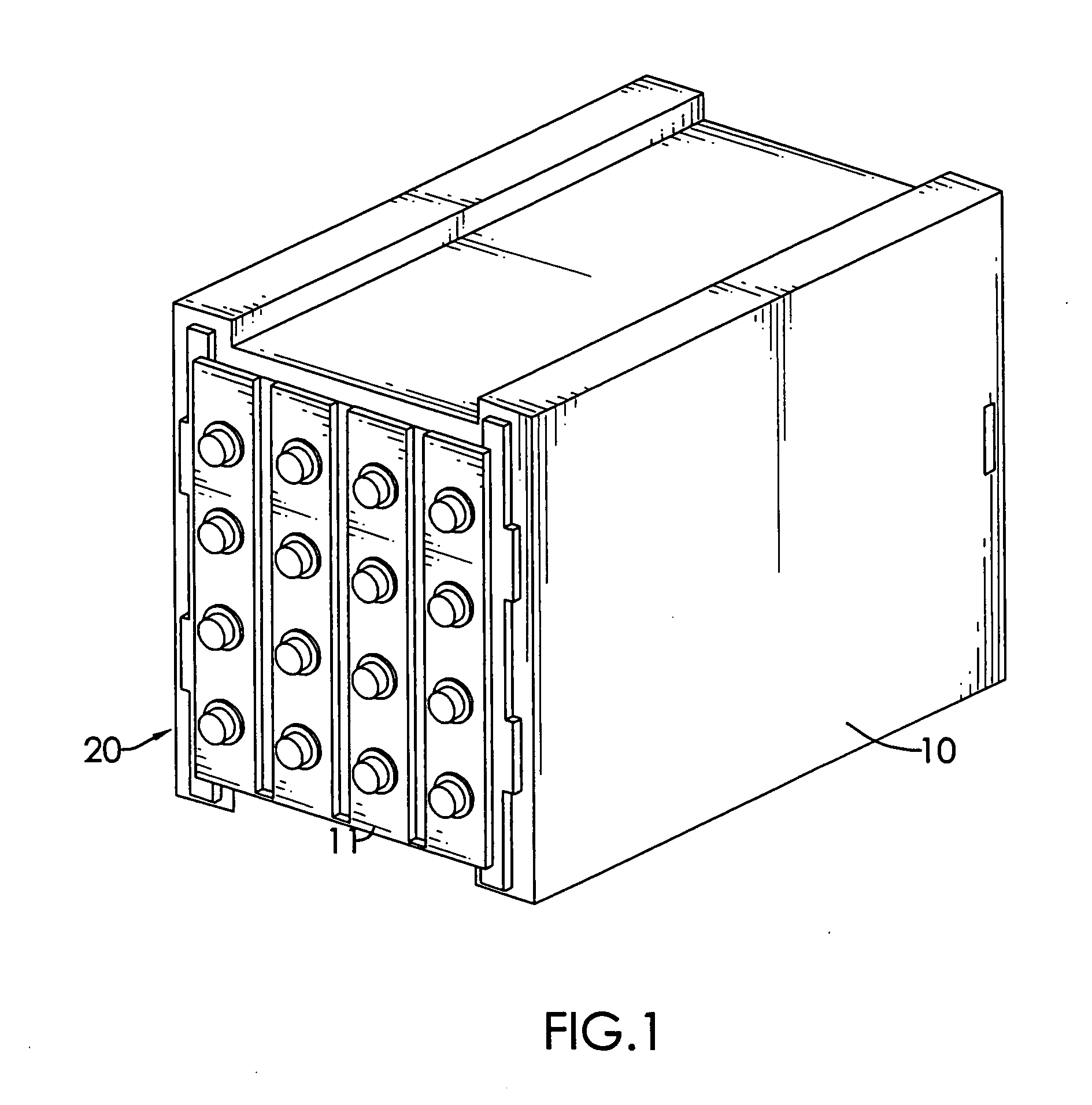
[0024]With reference to FIG. 1, a battery holder comprises a body (10) and multiple conductive components (20) in accordance with the present invention.

[0025]The body (10) is hollow and has a front, a rear, multiple setting holes, an opening and an optional panel (11). The setting holes are formed in the front of the body (10). The opening is formed in the rear of the body (10) and allows a battery to be inserted into the body (10). The panel (11) is mounted on the front of the body (10) and has multiple assembling holes. The assembling holes are formed through the panel (11) and respectively align with the setting holes.

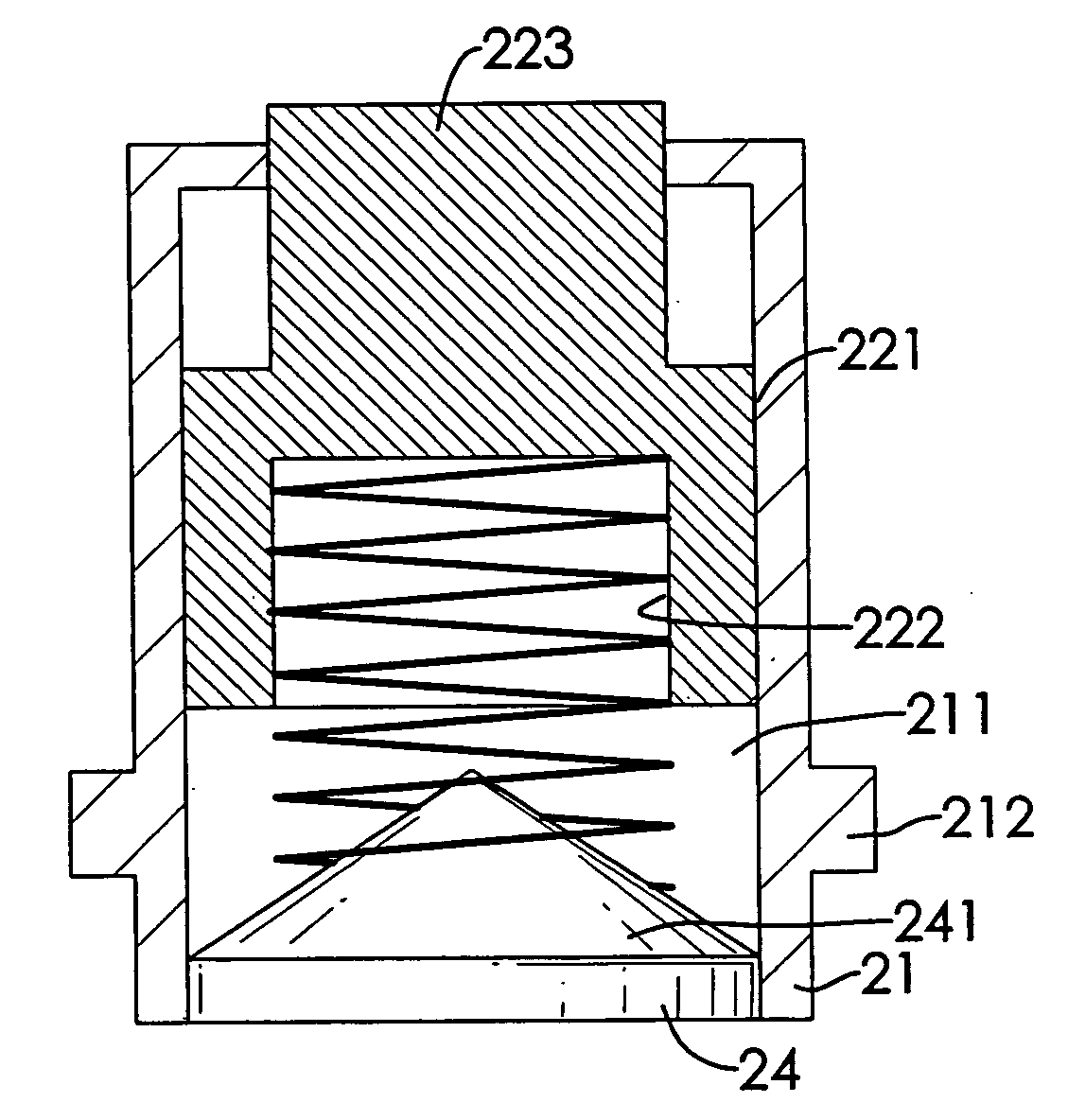
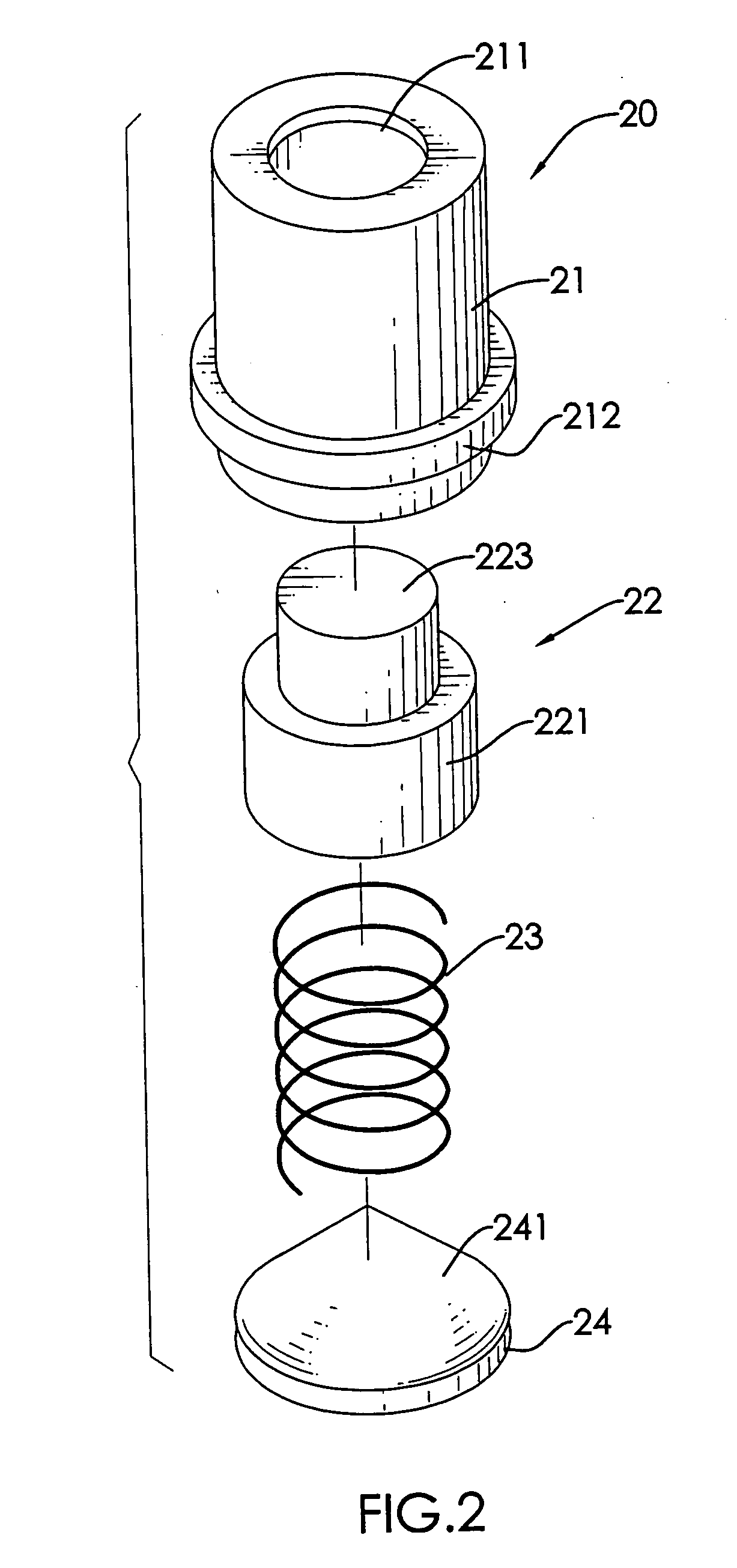
[0026]With further reference to FIGS. 2 and 3, the conductive components (20) are mounted respectively in the body (10). Each conductive component (20) has a housing (21), a conductor (22), a spring (23) and a base (24).

[0027]The housing (21) is conductive, is mounted in the corresponding setting hole of the body (10), may be mounted through the corresponding assemb...


PUM


Abstract

A conductive component has a housing and a conductor. The housing is conductive and has a contact end, a distal end, a through hole and an inner surface. The through hole is formed through the contact end and the distal end. The conductor is mounted movably in the through hole of the housing and has a distal end, a proximal end, a conducting portion and a side wall. The proximal end of the conductor is held in the through hole of the housing. The conducting portion is formed on and protrudes out from the proximal end of the conductor and protrudes out from the contact end of the housing. The side wall corresponds to and abuts the inner surface of the housing. Because the conductor has an increased surface to contact with the inner surface of the housing, the battery holder has an improved current tolerance.

Description

BACKGROUND OF THE INVENTION[0001]1. Field of the Invention[0002]The present invention relates to a conductive component, and more particularly to a conductive component with an improved current tolerance.[0003]2. Description of the Prior Arts[0004]With raising public awareness of environmental protection, usage of electric vehicles gradually increases. An electric vehicle usually requires a battery having electrodes to store electricity. Conventionally, the battery is mounted securely in the electric vehicle and the electrodes of the battery are connected securely. Therefore, the battery cannot be easily removed from the electric vehicle, causing difficulty in maintaining the electric vehicle. Thus a conventional battery holder has been designed for accommodating a battery and transmitting electricity from the battery to the electric vehicle.[0005]With reference to FIG. 6, the conventional battery holder comprises a body, an opening being formed on the body and multiple conventional...

Claims


Application Information

Patent Timeline
IPC IPC(8): H01M2/10H01B5/00H01M50/296
CPCH01M2/1083Y02E60/10H01M50/50H01M50/296
Inventor WANG, CHIEN-TUNG
Owner KENDOO TECH
Why Eureka
Try Eureka