Current Source with Power Supply Voltage Variation Compensation

Inactive Publication Date: 2009-02-05
IBM CORP
View PDF9 Cites 5 Cited by
  • Summary
  • Abstract
  • Description
  • Claims
  • Application Information

AI Technical Summary

Benefits of technology

[0016]In accordance with the present invention, an improved multipath current source is provided. In this current source, the gates of current controlled devices in both the reference and controlled current paths are connected to the output of a differential amplifying stage with one input coupled to the drain of the output control device in the reference current path and the other input connected to the drain of the control device in the controlled current path. This differential amplifier senses any difference between the two voltages V1 and V2 at the drains of both devices. This reduces the effect of a variation in the voltage supply voltage VDD on current in both paths. In the preferred embodiment, a third output path is fed current from the source VDD through an additional device that receives Vgs as its gate excitation. With this arrangement, the current control devices in both the reference arid controlled current paths can have the same current carrying capacity further reducing the affect of variations in VDD on current through the third output path.

Problems solved by technology

Past solutions to this problem all suffer from one common ailment: sensitivity to power supply voltage.
However, the circuit of U.S. Pat. No. 6,559,720 requires external input voltages while the one in U.S. Pat. No. 5,777,518 requires an ideal current source, as well as an external voltage reference to function and is still sensitive to power supply variations in that it does not provide for control the drains of all transistors.

Method used


Image

  • Current Source with Power Supply Voltage Variation Compensation
  • Current Source with Power Supply Voltage Variation Compensation

Examples


Embodiment Construction

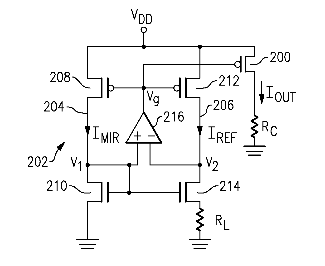
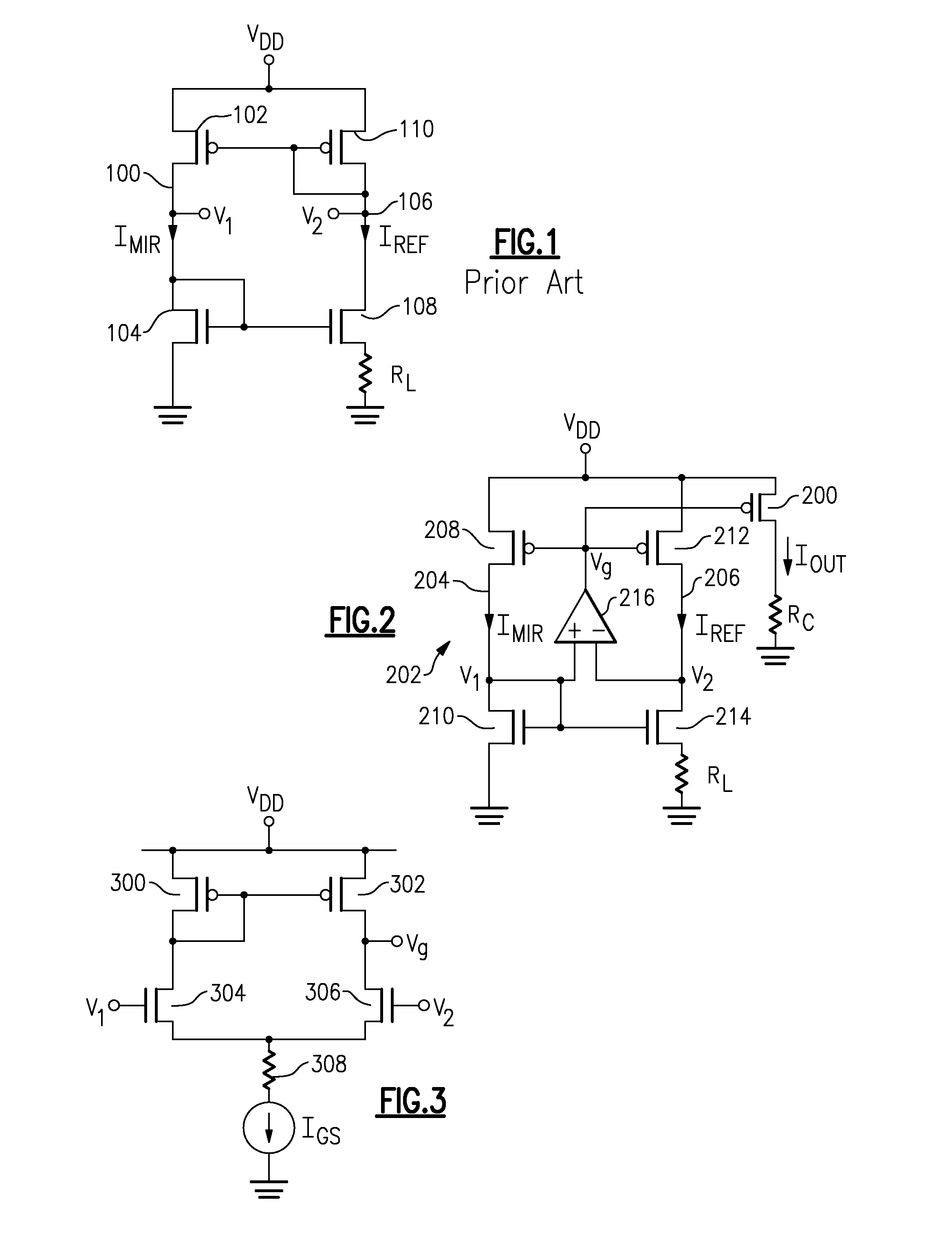
[0021]Referring now to FIG. 2, PFET 200 is connected in series with circuitry Rc between VDD and ground to control the current Iout through the circuitry Rc. A voltage Vg from a fixed current source 202 is used to control the current Iout. This current source 202 contains separate paths 204 and 206 between the voltage source VDD and ground. The first or reference current path 206 provides a reference current Iref while the second or controlled current path 204 provides a mirrored current Imir. In the reference current path 206, a current regulation PFET device 212 is connected in series with NFET device 214 and resistor RL between VDD and ground. In the mirrored current path current regulation PFET device 208 is connected in series with NFET device 210 between VDD and ground. The gates of PFET devices 208 and 212 are tied together to receive the same gate voltage Vg and thus closely match the currents Iref and Imir. The gates of NFET devices 210 and 214 are also tied together in ord...


PUM


Abstract

A multipath current source has separate reference current, control current and output current paths. Voltages in the reference current and control current paths are monitored. Any differences between those two voltages are fed to the gates of current control devices in the reference, control and output current paths to maintain the currents in all paths substantially constant with changes in supply voltage.

Description

FIELD OF THE INVENTION [0001]The present invention relates to power sources, more particularly to a constant current source with power supply voltage variation compensation.BACKGROUND OF THE INVENTION [0002]As technology advances, circuitry has to adapt to the higher tolerances that are present in modern lithographic processes. By controlling the transconductance of transistors, many analog circuits including amplifiers, current mode logic circuitry and I / Os are able to keep their parameters constant. Past solutions to this problem all suffer from one common ailment: sensitivity to power supply voltage. U.S. Pat. Nos. 4,890,052 and 6,727,748 both attempt to lower power supply sensitivity by adding cascaded transistors. Both of these patents disclose imperfect solution where the controlled current still changes with supply voltage. U.S. Pat. Nos. 6,559,720 and 5,777,518 also discloses circuits that attempt to control the power supply sensitivity. However, the circuit of U.S. Pat. No....

Claims


Application Information

Patent Timeline
IPC IPC(8): G05F3/20
CPCG05F3/262
Inventor SPERLING, MICHAEL A.
Owner IBM CORP
Why Eureka
Try Eureka