
Self-aligned short-channel electronic devices and fabrication methods of same

Active Publication Date: 2020-12-17
NORTHWESTERN UNIV
View PDF5 Cites 6 Cited by
  • Summary
  • Abstract
  • Description
  • Claims
  • Application Information

AI Technical Summary

Benefits of technology

This patent describes a method for making electronic devices using materials called van der Waals materials, specifically thin films of molybdenum disulfide (MoS2). The method allows for the fabrication of transistors with very small channels, which can be controlled independently to avoid certain effects associated with smaller channels. The method can be applied to a wide range of nanomaterials and can be used in parallel to make multiple devices. The method also allows for the fabrication of gated diodes that have complete control of both the p-type and n-type semiconductors, providing greater flexibility in device design. The method is scalable and can be used to make transistors with sub-diffraction channel lengths. Overall, the method represents a way to make more complex circuits using these new materials.

Problems solved by technology

Parallel self-aligned fabrication methods in modern silicon-based microelectronics have enabled sub-lithographic registration between processing steps, ultimately facilitating substantial advances in circuit complexity over the past few decades W. However, two-dimensional (2D) material devices have not yet exploited parallel self-aligned fabrication to achieve both short channels and large area fabrication while 2D materials have shown significant potential for digital and analog electronics due to their high mobilities, ultrathin geometry, and broad range of permutations in van der Waals heterojunctions (vdWHs) [2-9].
Similarly, the relative alignment of different layers in vdWHs has been inhibited by the diffraction-limited resolution of transfer and alignment methods.
Therefore, a heretofore unaddressed need exists in the art to address the aforementioned deficiencies and inadequacies.

Method used


Image

  • Self-aligned short-channel electronic devices and fabrication methods of same
  • Self-aligned short-channel electronic devices and fabrication methods of same
  • Self-aligned short-channel electronic devices and fabrication methods of same

Examples


Embodiment Construction

lass="d_n">[0063]The present invention will now be described more fully hereinafter with reference to the accompanying drawings, in which exemplary embodiments of the present invention are shown. The present invention may, however, be embodied in many different forms and should not be construed as limited to the embodiments set forth herein. Rather, these embodiments are provided so that this disclosure will be thorough and complete, and will fully convey the scope of the invention to those skilled in the art. Like reference numerals refer to like elements throughout.

[0064]The terms used in this specification generally have their ordinary meanings in the art, within the context of the invention, and in the specific context where each term is used. Certain terms that are used to describe the invention are discussed below, or elsewhere in the specification, to provide additional guidance to the practitioner regarding the description of the invention. For convenience, certain terms may...


PUM


Abstract

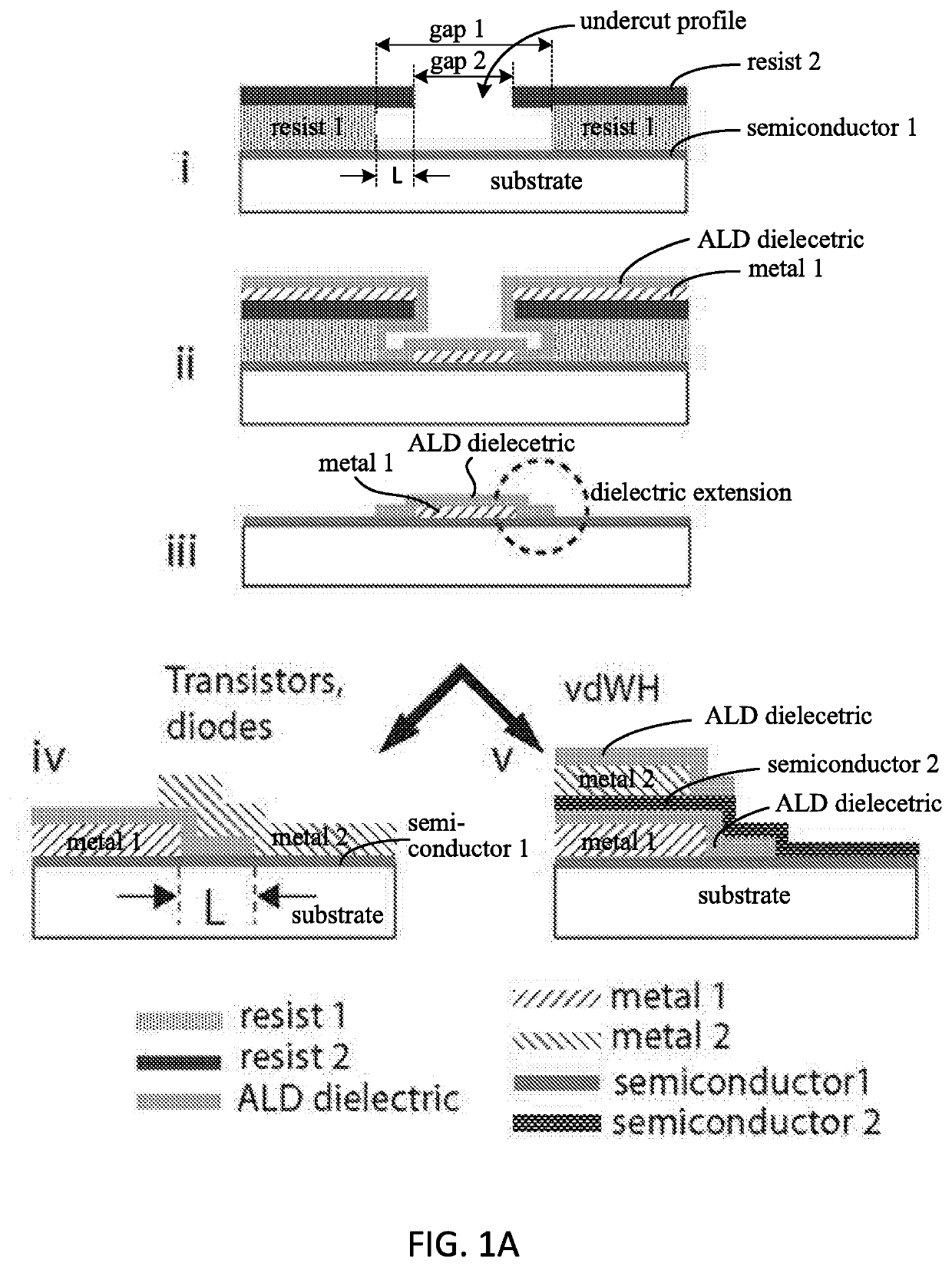
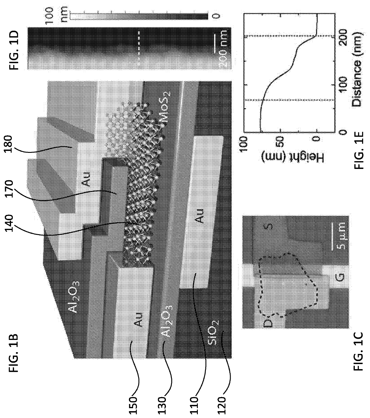
A self-aligned short-channel SASC electronic device includes a first semiconductor layer formed on a substrate; a first metal layer formed on a first portion of the first semiconductor layer; a first dielectric layer formed on the first metal layer and extended with a dielectric extension on a second portion of the first semiconductor layer that extends from the first portion of the first semiconductor layer, the dielectric extension defining a channel length of a channel in the first semiconductor layer; and a gate electrode formed on the substrate and capacitively coupled with the channel. The dielectric extension is conformally grown on the first semiconductor layer in a self-aligned manner. The channel length is less than about 800 nm, preferably, less than about 200 nm, more preferably, about 135 nm.

Description

CROSS-REFERENCE TO RELATED PATENT APPLICATION[0001]This application claims priority to and the benefit of U.S. provisional patent application Ser. No. 62 / 619,170, filed Jan. 19, 2018, entitled “SELF-ALIGNED VAN DER WAALS HETEROJUNCTION DIODES AND TRANSISTORS AND METHOD OF MAKING SAME,” by Vinod K. Sangwan, Megan E. Beck and Mark C. Hersam, which is incorporated herein in its entirety by reference.[0002]Some references, which may include patents, patent applications and various publications, are cited and discussed in the description of this invention. The citation and / or discussion of such references is provided merely to clarify the description of the present invention and is not an admission that any such reference is “prior art” to the invention described herein. All references cited and discussed in this specification are incorporated herein by reference in their entireties and to the same extent as if each reference was individually incorporated by reference. In terms of notati...

Claims


Application Information

Patent Timeline
IPC IPC(8): H01L29/76H01L29/24H01L29/45H01L29/51H01L21/02H01L21/78H01L51/05H01L51/10H01L51/00H01L29/66
CPCH01L21/02164H01L29/51H01L51/003H01L21/0262H01L51/0545H01L21/02521H01L21/02238H01L29/7606H01L21/02568H01L51/0562H01L21/02631H01L51/0048H01L51/105H01L29/66969H01L29/24H01L29/45H01L51/0008H01L21/7806H01L51/0525H01L27/0629H01L27/1288H01L29/778H01L29/78681H01L29/41733H01L29/42384H01L29/4908H01L29/78696H01L2029/42388H01L29/42356H01L29/861H01L29/1606H01L29/41725H10K10/468H10K10/84H10K10/466H10K10/472H10K10/486H10K71/16H10K71/80H10K85/221
Inventor HERSAM, MARK C.SANGWAN, VINOD K.BECK, MEGAN E.
Owner NORTHWESTERN UNIV
Learn More