Quick Release Toilet Mechanism

a toilet seat and quick release technology, applied in the field of quick release toilet seat bolt assembly, can solve the problems of affecting the cleaning or repair of the seat, the difficulty of using tools, and the inconvenience of consumers in removing or disassembling the seat, so as to prevent the seat from rotating

Inactive Publication Date: 2008-07-24
FUSION EXPERTS
View PDF5 Cites 17 Cited by
  • Summary
  • Abstract
  • Description
  • Claims
  • Application Information

AI Technical Summary

Benefits of technology

[0008]The present invention is directed to an easily removable bolt assembly that makes the assembly or disassembly of a toilet seat simple and quick.
[0009]To achieve this purpose, the present invention has an easily removable bolt assembly, comprising generally a bolt and a nut to fasten a toilet seat to a toilet base, wherein the bolt has a pivotal knob or bar handle that can be used to turn the bolt to thread it into the nut. The nut has an inner screw hole through its center for receiving the bolt. In an embodiment of the invention, the nut has a protruding square neck portion that can be inserted into a lock hole on the toilet base, such that rotation of the nut in the lock hole is restricted. In this way the bolt on the upper part of the toilet is can be directly interlocked with the nut without the use of any tool, thus making it easy to lock and fasten the toilet seat assembly to the toilet base.
[0012]In yet another embodiment of the invention, the fastening hinge has a hole with split channel, which allows the bolt to be accommodated such that the toilet seat can be installed or removed without disassembling the bolt assembly.

Problems solved by technology

Because the location of the nut in the lower part of the toilet base is not directly visible from above, the manipulation and use of the tools for installation or disassembly of the seat can be very difficult.
In particular, since toilets are often installed near a wall, it is all the more difficult to use tools because the bolts and nuts are not readily accessible.
For these reasons, due to the inconvenience of removing or installing a traditional toilet seat assembly, it is a hassle for consumers to remove or install seats for cleaning or repair.
However, since the stem portion must be made of a plastic material, it may become easily deformed or may even break after being subject to prolonged pressure.
However, since space insert leaves and space protrusions are placed on the expandable pipe and rubber liner to take pressure from the nut, the space insert leaves expand outwards and are stuck under the positioning hole of the lip of the toilet.
Not only is it impossible for the insert leaves in the lower half of the expandable pipe to be restored to shape when it becomes deformed after use, but the security of the fastening method by outward expansion is untested.
Also, the greatest inconvenience is that it is complex in structure and designs and requires the use of tools and screw locks.

Method used


Image

  • Quick Release Toilet Mechanism
  • Quick Release Toilet Mechanism
  • Quick Release Toilet Mechanism

Examples


first embodiment

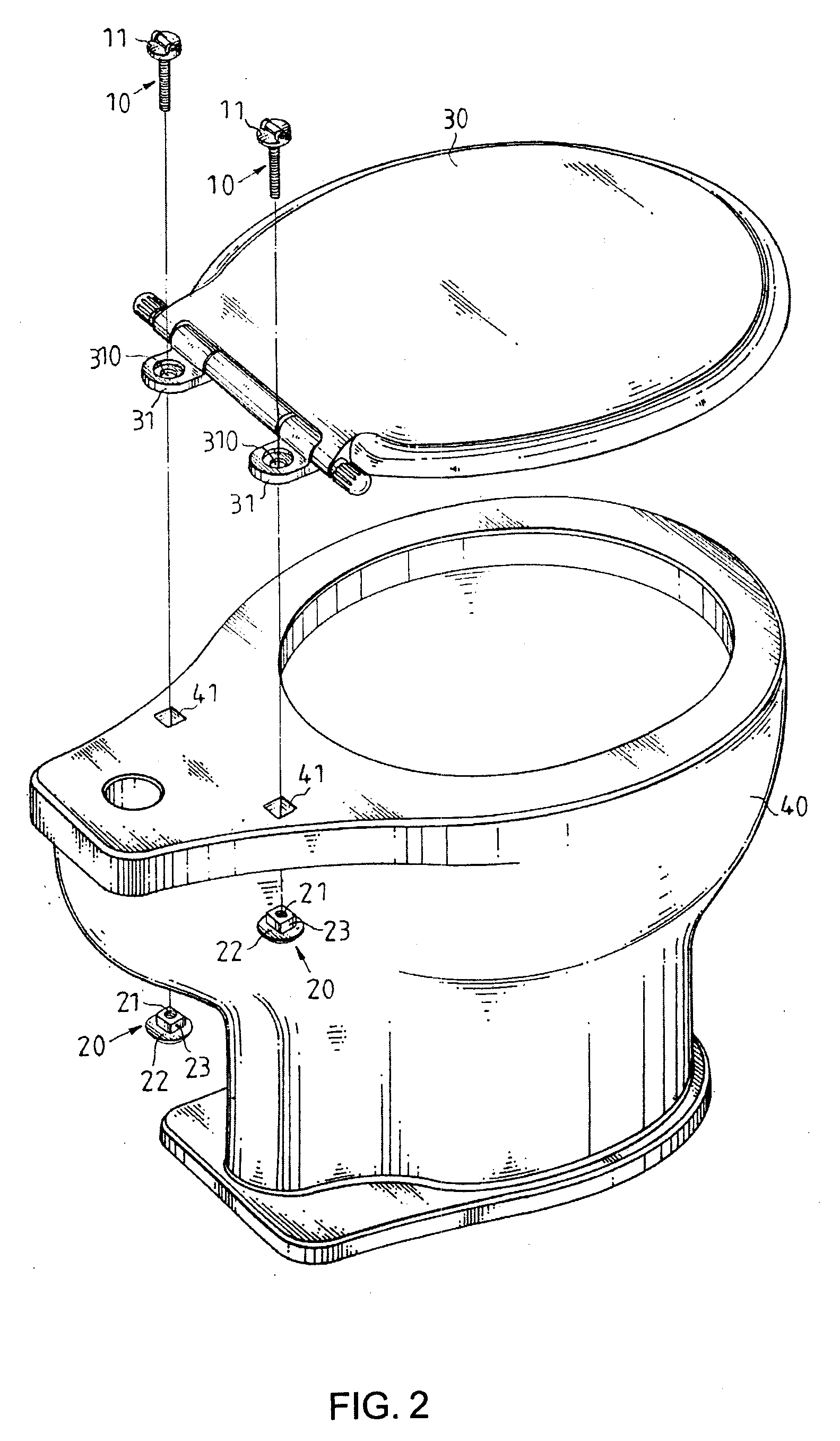
[0028]As further illustrated in FIG. 3, bolt 10 passes through hole 310 in fastening hinge 31. Fastening hinge 31 is coaxially aligned with lock hole 41 in the toilet base 40. As shown in both FIGS. 2 and 3, in a first embodiment lock hole 41 is square shaped to accommodate nut 20. Nut 20 has domed head 22 with a square protruding neck 23 and a threaded hole 21. Nut 20 also has a flat side with a larger diameter presses up against the outside of lock holes 41 when the bolt 10 and nut 20 are assembled. In the present embodiment, the protruding neck 23 and lock hole 41 are square in shape so that rotation of nut 20 in lock hole 41 is restricted. Though protruding neck 23 of nut 20 functions to restrict rotation in square lock hole 41, its shape is not limited to a square only. Triangles, polygons, ovals and various irregular geometric shapes can all serve the same function.

[0029]Accordingly, to install toilet seat 30, bolt 10 passes through hole 310 in fastening hinge 31 to engage thr...

second embodiment

[0030]FIGS. 7˜9 show the present invention. In the second embodiment, bolt assembly A′ is comprised of a bar handle 113, bolt 10a, washer 114, and nut 20. Bar handle 113 has an eccentric pivotally connecting end 1130 with a spanning section 11a and a hole therein as shown in FIG. 8. Bar handle 113 can be fastened to bolt 10a by mounting connecting end 1130 onto the head of bolt 10a with a pin or dowel as shown. Bolt 10a is passed through washer 114, hole 310 of fastening hinge 31, and lock hole 41 to engage nut 20. As shown in FIG. 9, bar handle 114 can be turned to tighten bolt 10a so as to clamp fastening hinge 31 to toilet base 40.

third embodiment

[0031]the invention is shown in FIG. 10, wherein fastening hinge 31a has hole 310 with split channel 311. Split channel 311 allows bolt 10a to be accommodated such that toilet seat assembly 10 can be installed or removed without disassembling bolt assembly A′.

[0032]The fourth and fifth embodiments of the present invention are shown in FIG. 11 and FIG. 12, respectively. In both embodiments, lock hole 41a on the toilet base is round. Fastening hinge 31b has a connecting insert 312 for insertion into lock hole 41a. Connecting insert 312, which protrudes from the bottom of fastening hinge 31b, has clamp hole 313 that extends through connecting insert 312 to form split opening 3120 with two flat sides as shown in FIG. 11. Insert connecting end 312 is inserted into lock hole 41a to engage with nut 20a. Correspondingly, nut 20a has neck 23a with two flat sides 230. When nut 20a is inserted into clamp hole 313, the flat sides 230 on neck 23a mate with the flat sides in split opening 3120, s...


PUM


Abstract

The invention relates to a removable bolt assembly for fastening a toilet seat to a commode using a knob or bar handle. The knob or bar handle, pivotally mounted to the bolt, can be used to twist or clamp the bolt into engagement with a nut that is inserted through a hole in the toilet. The hole in the toilet can be circular or noncircular. Where the hole is noncircular, the nut has a corresponding noncircular geometric neck so as to prevent it from rotating in the hole. Where the hole is circular, a fastening hinge having a connecting insert can be used to prevent rotation of the nut when it is engaged with the connecting insert. In this way the bolt is directly interlocked with the nut without the use of any tool, thereby making it easy to lock and fasten the seat to the commode.

Description

PRIORITY INFORMATION[0001]This application claims priority to Taiwan Patent Application No. 096201283, filed on Jan. 23, 2007, and China Patent Application No. 200720066709.7, filed on Jan. 26, 2007.FIELD OF THE INVENTION[0002]The present invention relates to a bolt assembly structure capable of clamping and fastening a part to be locked easily without the help of any tool. More particularly, it refers to a bolt assembly for fastening a toilet seat.BACKGROUND OF THE INVENTION[0003]Toilet seat assembly typically includes a seat and a cover plate, wherein the seat assembly is pivotally mounted to the commode or toilet base by a pair of pivotally fastening hinges located at the rear of the seat for interlocking with the base. To install the seat assembly on the base, it is common to use a bolt and nut combination to clamp the fastening hinges onto the base. The traditional assembly method requires two sets of tools working concurrently both on the upper end and lower end of the toilet ...

Claims


Application Information

Patent Timeline
Patent Type & Authority Applications(United States)
IPC IPC(8): A47K13/24
CPCA47K13/24A47K13/26
Inventor SHIAU, DANIEL
Owner FUSION EXPERTS
Why Eureka
Try Eureka