Rotary electric shaver and inner cutter therefor

a rotary electric shaver and inner cutter technology, applied in the direction of metal working apparatuses, etc., can solve the problems of poor durability and noise, deterioration of the workability of press-punch machining and bend machining and the like, and difficulty in cleaning the inner cutter, so as to achieve the effect of making the rigidity of the cutter blades smaller, facilitating displacement and increasing the value of the invention

a rotary electric shaver and inner cutter technology, applied in the direction of metal working apparatuses, etc., can solve the problems of poor durability and noise, deterioration of the workability of press-punch machining and bend machining and the like, and difficulty in cleaning the inner cutter, so as to achieve the effect of making the rigidity of the cutter blades smaller, facilitating displacement and increasing the value of the invention

US20080172881A1Inactive Publication Date: 2008-07-24IZUMI PROD CO

Image

  • Rotary electric shaver and inner cutter therefor
  • Rotary electric shaver and inner cutter therefor
  • Rotary electric shaver and inner cutter therefor

Examples


Embodiment Construction

[0049]In the present invention, the inner cutter 56 is used in combination with an outer cutter 12 instead of the inner cutter 10 shown in FIG. 13. For this reason, the same reference numerals are used for parts that are identical to those in FIG. 13, and the descriptions thereof are not repeated hereinafter.

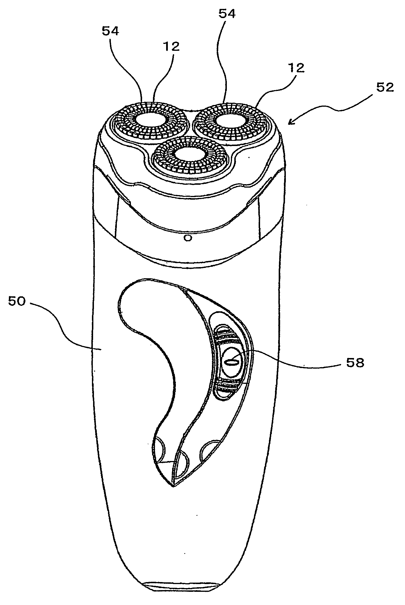
[0050]In FIG. 1, the reference numeral 50 is a shaver main body, and 52 refers to a head unit. The head unit 52 is detachably attached to the upper part of the shaver main body 50. In the head unit 52, three sets of cutter units 54 are provided. Each cutter unit 54 is comprised of an inner cutter 56 (see FIG. 3) and a disk-shaped outer cutter 12, and the outer cutters 12 of the three cutter units 54 are provided on a substantially triangular upper surface of the head unit 52 so that they can sink in.

[0051]The inner cutters 56 are rotationally driven by an electric motor (not shown) housed inside the shaver main body 50 and slide against the inside lower surfaces (inner surfaces)...


PUM


Abstract

An inner cutter including a circular hub unit, which is coupled to a rotary drive shaft, and a ring-shaped inner cutter main unit, which is secured to the hub unit and is formed with cutter blades standing up from their lower portions with the upper parts sliding against the inside lower surface of the outer cutter; and the cutter blades being formed with reduced cross-sectional portions that have a dimension in the radial direction of circular hub unit (or of the ring-shaped inner cutter main body) made smaller than a dimension in the radial direction of blade tip ends.

Description

BACKGROUND OF THE INVENTION[0001]1. Field of the Invention[0002]The present invention relates to a rotary electric shaver having a substantially disk-shaped outer cutter(s) which has numerous hair introduction openings in the upper surface, and an inner cutter(s), which is rotated while sliding against the inner surface of the outer cutter(s), and further relates to an inner cutter used in this electric shaver.[0003]2. Description of the Related Art[0004]One type of widely known rotary electric shaver includes an outer cutter(s), which is substantially disk-shaped and in which a ring shaped track (channel) is formed in the inner surface thereof and numerous hair introduction openings (slits, for example) are formed so as to cut across the track and to open to the upper surface of the outer cutter, and an inner cutter(s), which is provided so that it is rotated while the blades (cutter blades) thereof sliding against the track of the outer cutter, as disclosed in, for instance, Japan...

Claims


Application Information

Patent Timeline
24 Jul 2008
Publication
US20080172881A1
IPC
B26B19/14; B26B19/04
CPC
B26B19/141; B26B19/145; B26B19/143
Inventors
OKABE, MASAKI