Structure for mounting batteries onto electric vehicles

a technology for electric vehicles and structures, applied in the direction of electric devices, vehicle sub-unit features, cell components, etc., can solve the problems of difficulty in keeping the battery box (30) in the correct position, and achieve the effect of improving the crash-resistant capability of the battery mounted and preventing increased weight and cos

Active Publication Date: 2008-07-24
MITSUBISHI MOTORS CORP
View PDF26 Cites 40 Cited by
  • Summary
  • Abstract
  • Description
  • Claims
  • Application Information

AI Technical Summary

Benefits of technology

[0010]The present invention has been developed in consideration of this situation, and it is therefore an object of the invention to provide a structure for mounting a battery onto an electric vehicle to improve the crash-resistant capability of the battery mounted on the electric vehicle while preventing increased weight and cost.

Problems solved by technology

However, by the technique of the related document 1, it is difficult to keep the battery box (30) in the correct position if a electric vehicle (10) crashes.

Method used


Image

  • Structure for mounting batteries onto electric vehicles
  • Structure for mounting batteries onto electric vehicles
  • Structure for mounting batteries onto electric vehicles

Examples


Embodiment Construction

[0038]The embodiment of the present invention will now be described with reference to the accompanying drawings.

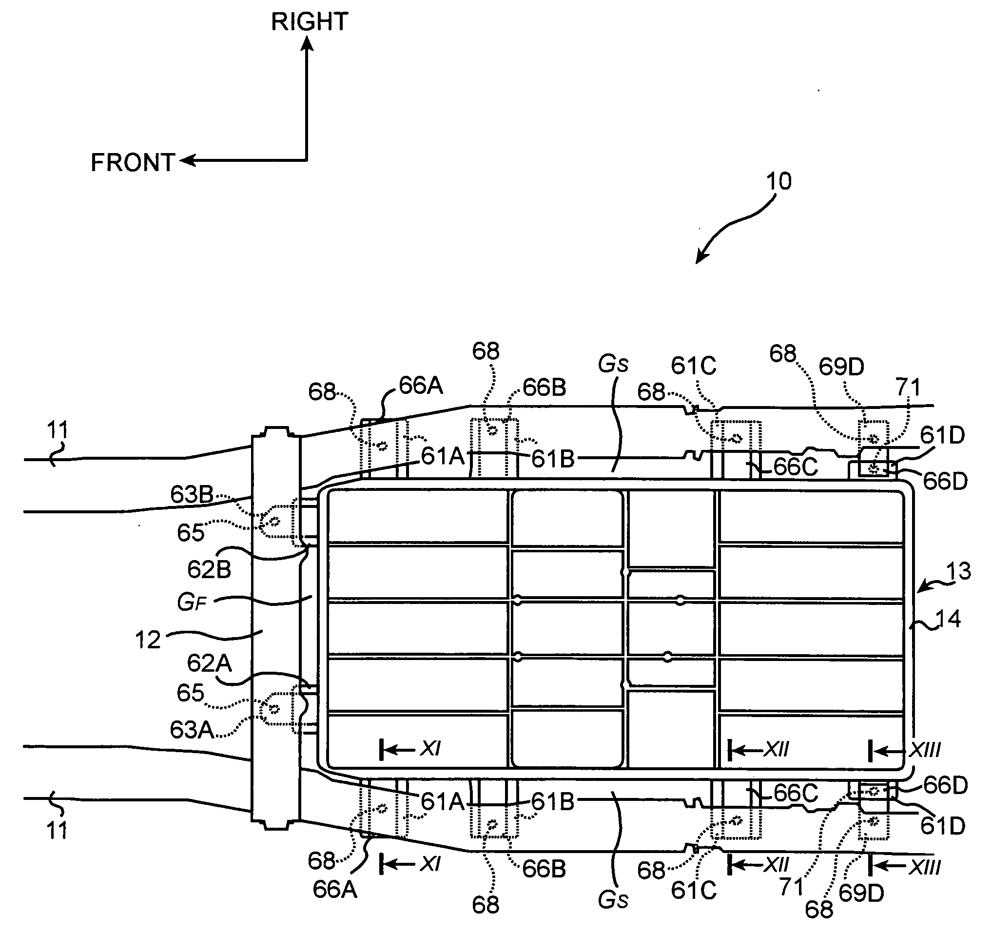
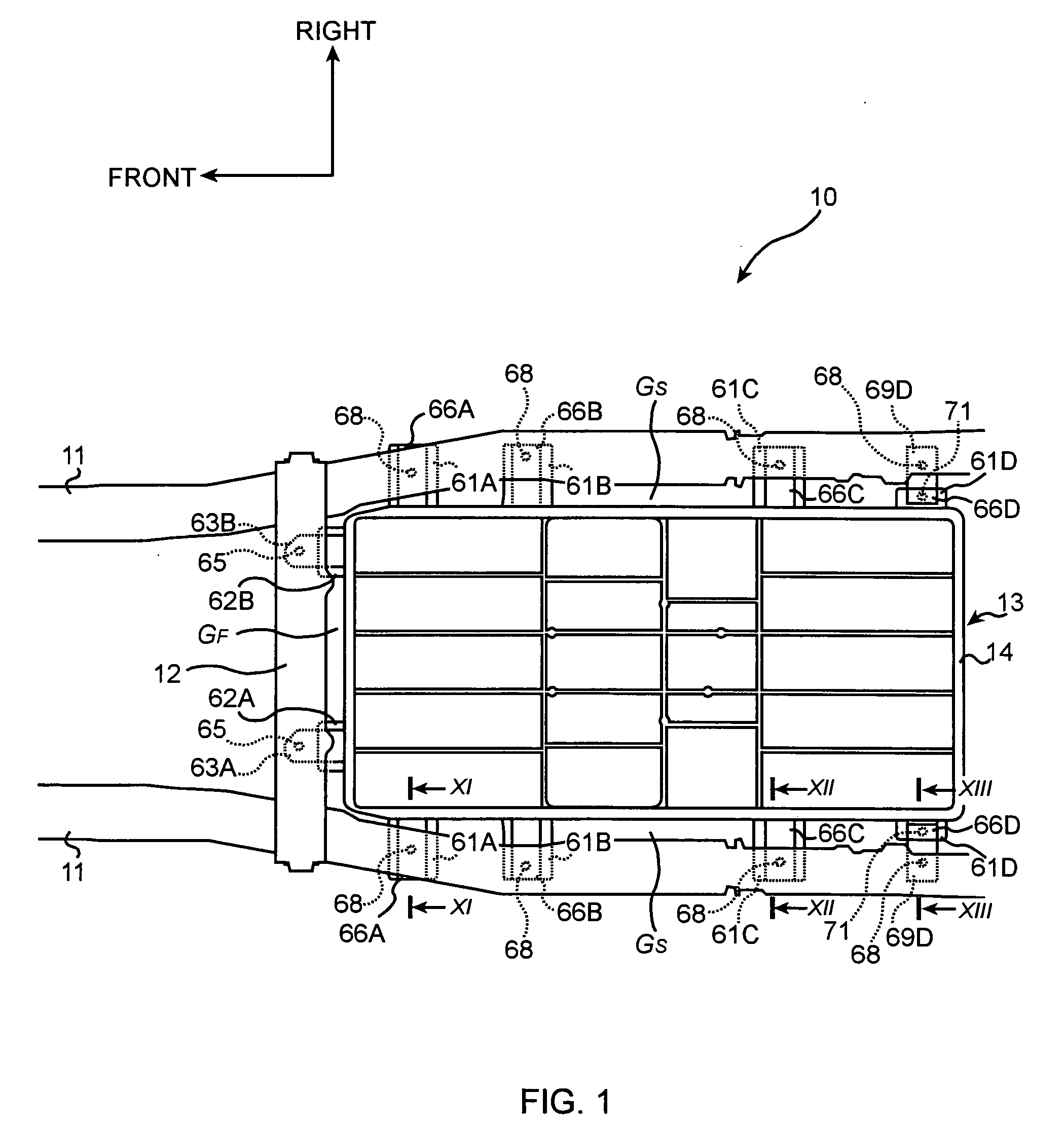
[0039]As shown in FIG. 1, side members (also called ‘body members’ or ‘first body members’) 11 and 11 are mounted on the left and right sides of an electric vehicle 10. The side members 11 and 11 extend in the longitudinal direction of the electric vehicle 10.

[0040]Further, a battery cross member (also called ‘body member’ or ‘second body member’) 12, which extends in the transversal direction (left-right direction) and which connects the pair of side members 11 and 11, is also mounted in the electric vehicle 10.

[0041]The side members 11 and 11 and the battery cross member 12 are iron, and constitute a body of the electric vehicle 10.

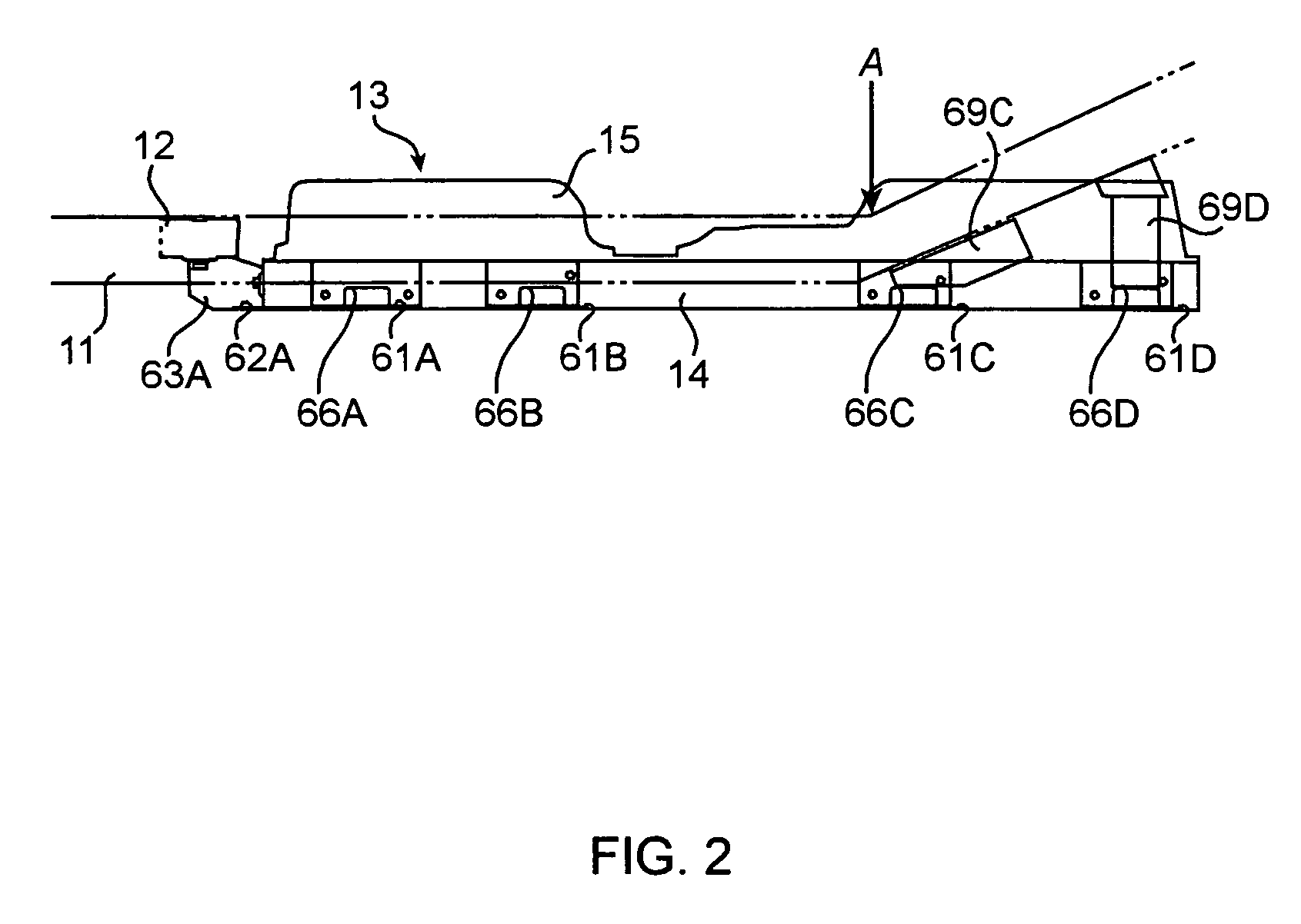
[0042]At a position between the pair of side members 11 and 11 and rear of the battery cross member 12, a battery case 13 is disposed. The battery case 13, which is made from polybutylene resin including glass fibers, contains and holds batter...


PUM

PropertyMeasurementUnit
voltageaaaaaaaaaa
voltageaaaaaaaaaa
structureaaaaaaaaaa

Abstract

A structure for mounting a battery onto an electric vehicle comprises: a body member forming a body of the electric vehicle; a battery case containing a battery; a supporting member, which is projected outward from the battery case and is disposed under the body member, fixed to a bottom of said battery case; and a clash-proof block connecting between the battery case and the body member.

Description

BACKGROUND OF THE INVENTION[0001](1) Field of the Invention[0002]The present invention relates to a structure for mounting a battery onto an electric vehicle.[0003](2) Description of Related Art[0004]Structures for mounting batteries onto electric vehicles have been known in the art. The following related document 1 discloses an example of such a structure.[0005]In the related document 1, as shown in FIGS. 1-4, a battery box (30) is fixed to side frames (20a and 20b) by front fixing portions (56a) and rear fixing portions (56b).[0006][Related Document 1] Japanese Laid-open Publication H05-193369[0007]However, by the technique of the related document 1, it is difficult to keep the battery box (30) in the correct position if a electric vehicle (10) crashes.[0008]For example, if a front end of the electric vehicle (10) is subject to impact, the battery box (30) moves forward due to inertia. Particularly, as the battery box (30) contains heavy batteries, the kinetic energy of the batter...

Claims


Application Information

Patent Timeline
Patent Type & Authority Applications(United States)
IPC IPC(8): B60K1/04B60R16/04H01M2/10
CPCB60K1/04B60K2001/0416B60L3/0007B60L11/1879B60R16/04Y02T10/7005Y02T10/705B60L11/1877B60L50/64B60L50/66B60Y2410/115Y02T10/70
Inventor TAKASAKI, SEIICHI
Owner MITSUBISHI MOTORS CORP
Why Eureka
Try Eureka