Novel automobile front anti-collision beam assembly

A front anti-collision beam and crossbeam assembly technology, which is applied to vehicle components, vehicle safety arrangements, bumpers, etc., can solve problems such as safety threats to occupants in the vehicle, cracked solder joints of the crossbeam, and fracture of the crossbeam to improve energy absorption in collisions Excellent impact resistance, excellent impact resistance, and easy disassembly

Active Publication Date: 2019-01-04
SOUTH CHINA UNIV OF TECH
View PDF7 Cites 7 Cited by
  • Summary
  • Abstract
  • Description
  • Claims
  • Application Information

AI Technical Summary

Problems solved by technology

In the low-speed frontal collision test of the anti-collision beam, it was found that the solder joint in the middle of the beam itself was broken, resulting in a fracture in the middle of the beam
This phenomenon not only reduces the strength of the beam, but also the collision force cannot be evenly transmitted to the energy-absorbing boxes on both sides through the beam, and the energy-absorbing boxes cannot be crushed to absorb the collision energy, which reduces the passive safety performance of the car
Due to the narrow space at the front of the car body, the installation space of the front anti-collision beam is limited, and the length of the energy-absorbing box is not enough
In the low-speed frontal collision test under extreme conditions, the anti-collision beam cannot completely absorb the collision energy. After the energy-absorbing box reaches the compaction stage, the collision force will be directly transmitted to the vehicle body, which poses a serious threat to the safety of the occupants in the vehicle. caused more serious damage to the front of the car

Method used


Image

  • Novel automobile front anti-collision beam assembly
  • Novel automobile front anti-collision beam assembly
  • Novel automobile front anti-collision beam assembly

Examples


Embodiment Construction

[0028] In order to enable researchers in the field to further understand the present invention and related technical contents, the present invention will be further described below in conjunction with the accompanying drawings.

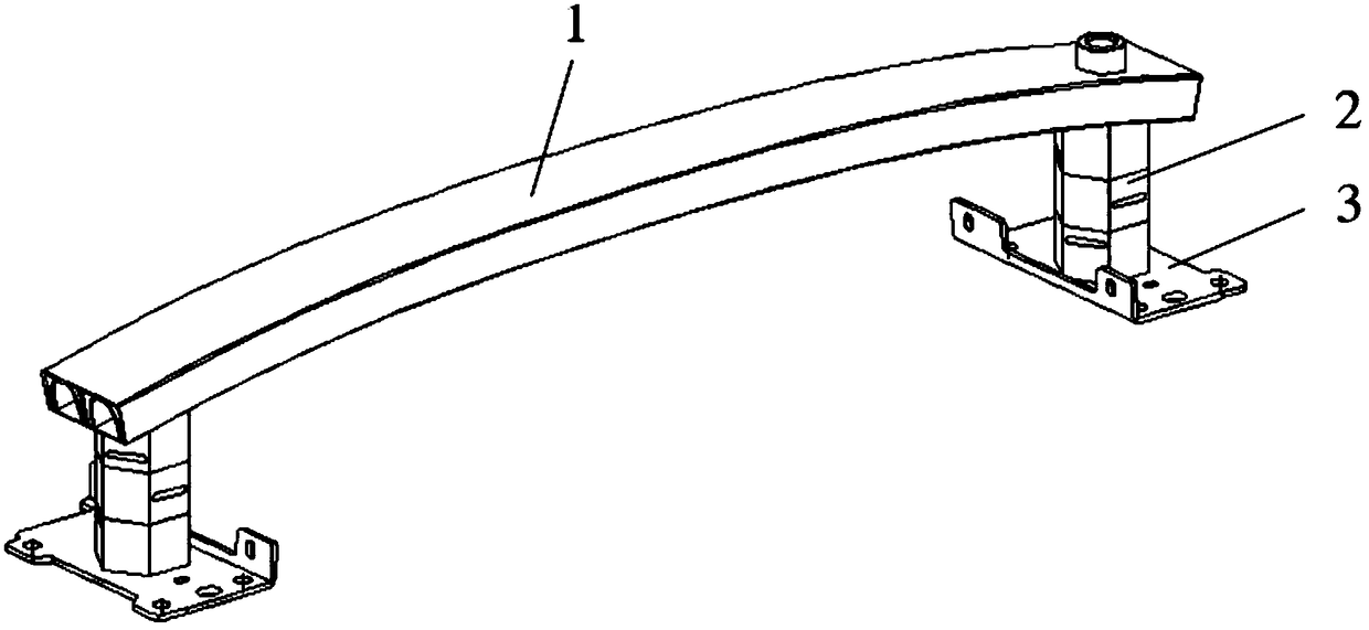
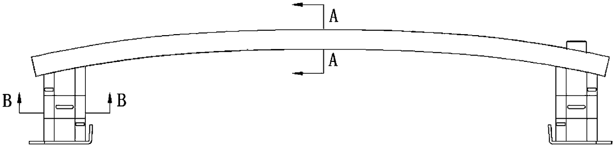
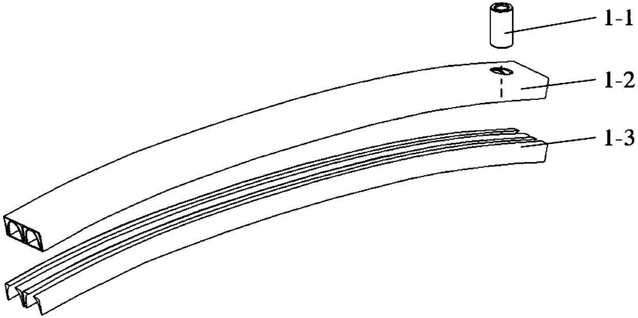
[0029] Such as figure 1 As shown, a new type of automobile front anti-collision beam assembly includes a beam assembly 1, two energy-absorbing box assemblies 2 and two connecting plates 3, the inner side of the beam is welded to one end of the two energy-absorbing box assemblies 2, and the two The other end of the energy-absorbing box assembly 2 is welded to the connection plate, and the connection plate is fastened to the front longitudinal beam assembly of the vehicle body by bolts. The cross beam assembly 1 is filled with several layers of functional gradients whose density decreases from the middle to both ends. material, the energy-absorbing box assembly 2 includes an energy-absorbing box, and the energy-absorbing box is made of several layers of...


PUM


Abstract

The invention discloses a novel automobile front anti-collision beam assembly including a beam assembly, two energy absorbing box assemblies, and two connecting plates. The inner side of the beam is welded to one end of the two energy absorbing box assemblies, and the other end of the two energy absorbing box assemblies is welded to the connecting plate, and the connecting plate is fastened to thefront side frame assembly of the vehicle body by bolts. The cross beam assembly is filled with a plurality of layers of functionally graded material whose density decreases from the middle to the twoends, the energy absorbing box assembly includes an energy absorbing box made of a plurality of layers of functionally graded material whose yield strength increases layer by layer in a direction away from the cross beam assembly, and the energy absorbing box is filled with a plurality of layers of functionally graded material whose density increases layer by layer in a direction away from the cross beam assembly. The cross beam and the energy absorption box of the invention are filled with aluminum foam with functional gradient distribution, so that the bending strength and the collision energy absorption effect of the anti-collision beam can be improved and the self-weight of the anti-collision beam can be reduced at the same time, and the anti-collision beam has the advantages of excellent anti-collision performance, simplicity, practicability, convenience for disassembly and the like.

Description

technical field [0001] The invention belongs to the technical field of automobile collision safety, in particular to a novel automobile front anti-collision beam assembly. Background technique [0002] With the continuous increase of car ownership, the traffic accidents of car collisions are also increasing, and the problem of car safety is becoming more and more prominent. When a traffic accident occurs, the automobile anti-collision beam is the first barrier to protect the safety of the occupants, and it is an important part of the automobile passive safety system. Under a low-speed collision of no more than 15km / h, a good anti-collision beam should be able to maximize the safety of the occupants in the vehicle while minimizing the damage to the vehicle's vulnerable parts. In the low-speed frontal collision test of the anti-collision beam, it was found that the solder joint in the middle of the beam itself was broken, resulting in a fracture in the middle of the beam. Th...

Claims


Application Information

Patent Timeline
Patent Type & Authority Applications(China)
IPC IPC(8): B60R19/18B60R19/34
CPCB60R19/18B60R19/34B60R2019/182
Inventor 黄文舜上官文斌李旻
Owner SOUTH CHINA UNIV OF TECH
Why Eureka
Try Eureka