System and method for ESD protection

a technology of esd protection and protection system, applied in the direction of emergency protection arrangement for limiting excess voltage/current, pulse technique, semiconductor/solid-state device details, etc., can solve the problems of radio signal weakness, distortion of signal capture, and complex design task of receiver design

Inactive Publication Date: 2008-07-24
AVAGO TECH INT SALES PTE LTD
View PDF38 Cites 20 Cited by
  • Summary
  • Abstract
  • Description
  • Claims
  • Application Information

AI Technical Summary

Benefits of technology

[0009]The IC bonding pads are constructed with a reduced area, and number of layers over a salicided diffusion implant to reduce capacitance.

Problems solved by technology

The design of a receiver is one of the most complex design tasks in electrical engineering.
The process of capturing the signal creates distortion that must be accounted for in the design of the radio receiver.
Radio signals are often extremely weak and if noise is present in the circuit, the signal, even though satisfactorily received, can be easily lost in this noise floor.
Radio signals in a receiver tend to be of small amplitude and high frequency and are therefore susceptible to distortion caused by capacitive loading by standard ESD control methods.

Method used


Image

  • System and method for ESD protection
  • System and method for ESD protection
  • System and method for ESD protection

Examples


Embodiment Construction

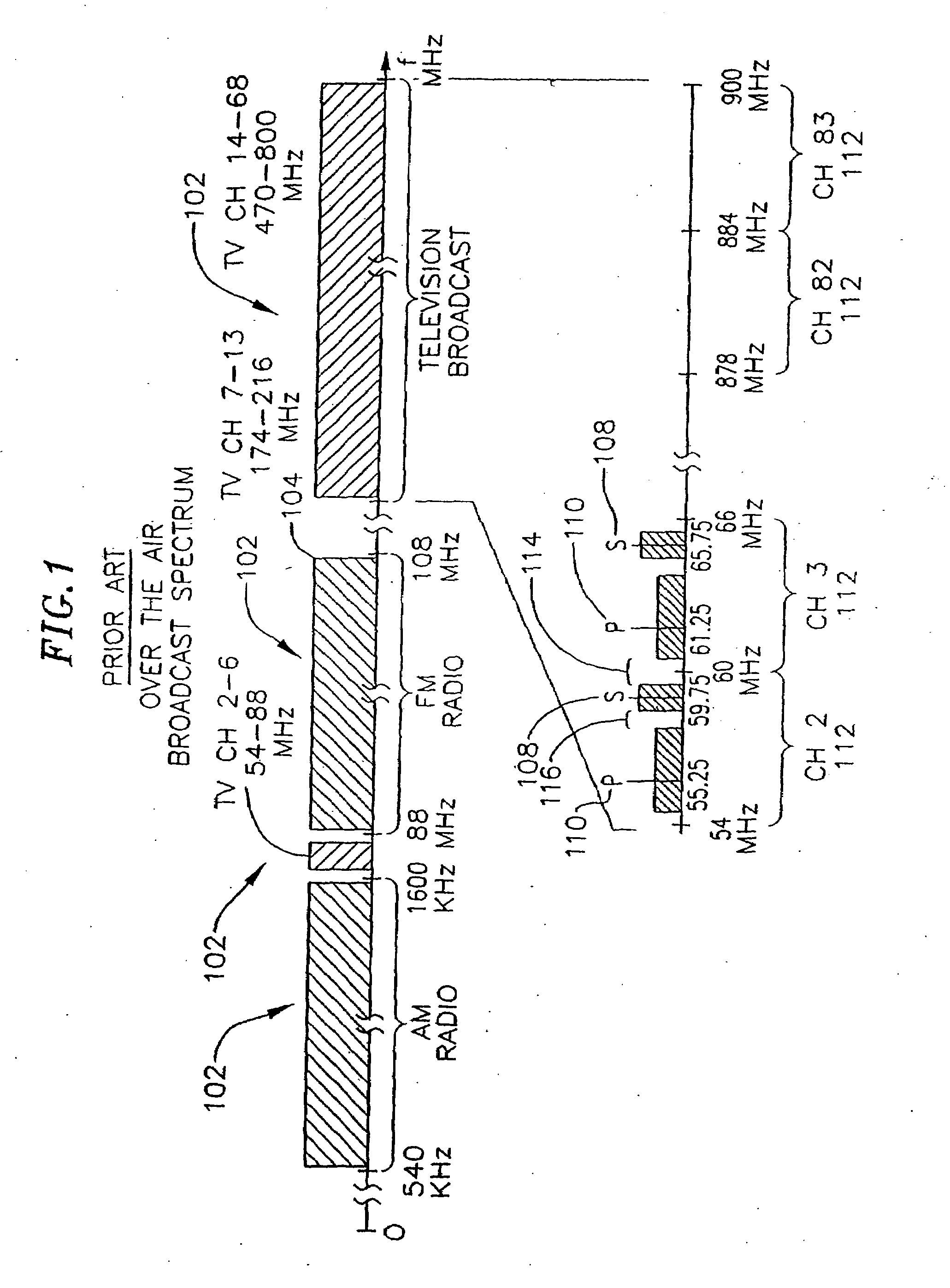
[0084]FIG. 1 is an illustration of a portion of the radio frequency spectrum allocations by the FCC. Transmission over a given media occurs at any one of a given range of frequencies that are suitable for transmission through a medium. A set of frequencies available for transmission over a medium are divided into frequency bands 102. Frequency bands are typically allocations of frequencies for certain types of transmission. For example FM radio broadcasts, FM being a type of modulation, is broadcast on the band of frequencies from 88 MHz to 108 MHz 104. Amplitude modulation (AM), another type of modulation, is allocated the frequency band of 540 kHz to 1,600 kHz 106. The frequency band for a type of transmission is typically subdivided into a number of channels. A channel 112 is a convenient way to refer to a range of frequencies allocated to a single broadcast station. A station broadcasting on a given channel may transmit one or more radio frequency (RF) signals within this band t...


PUM


Abstract

An integrated receiver with channel selection and image rejection substantially implemented on a single CMOS integrated circuit is described. A receiver front end provides programmable attenuation and a programmable gain low noise amplifier. Frequency conversion circuitry advantageously uses LC filters integrated onto the substrate in conjunction with image reject mixers to provide sufficient image frequency rejection. Filter tuning and inductor Q compensation over temperature are performed on chip. The filters utilize multi track spiral inductors. The filters are tuned using local oscillators to tune a substitute filter, and frequency scaling during filter component values to those of the filter being tuned. In conjunction with filtering, frequency planning provides additional image rejection. The advantageous choice of local oscillator signal generation methods on chip is by PLL out of band local oscillation and by direct synthesis for in band local oscillator. The VCOs in the PLLs are centered using a control circuit to center the tuning capacitance range. A differential crystal oscillator is advantageously used as a frequency reference. Differential signal transmission is advantageously used throughout the receiver. ESD protection is provided by a pad ring and ESD clamping structure that maintains signal integrity. Also provided are shunts at each pin to discharge ESD build up. The shunts utilize a gate boosting structure to provide sufficient small signal RF performance, and minimal parasitic loading.

Description

CROSS-REFERENCE TO RELATED APPLICATIONS[0001]This application claims the benefit of U.S. Provisional Patent Application No. 60 / 116,003 filed Jan. 15, 1999; U.S. Provisional Application No. 60 / 117,322 filed Jan. 26, 1999; and U.S. Provisional Application No. 60 / 122,754 filed Feb. 25, 1999; the contents of which are hereby incorporated by reference.[0002]This application is a continuation-in-part application of application Ser. No. 09 / 439,101 (B600:33756), filed Nov. 12, 1999, the disclosure of which is incorporated herein by reference.BACKGROUND OF THE INVENTION[0003]Radio receivers, or tuners, are widely used in applications requiring the reception of electromagnetic energy. Applications can include broadcast receivers such as radio and television, set top boxes for cable television, receivers in local area networks, test and measurement equipment, radar receivers, air traffic control receivers, and microwave communication links among others. Transmission of the electromagnetic ener...

Claims


Application Information

Patent Timeline
Patent Type & Authority Applications(United States)
IPC IPC(8): H02H9/00
CPCH01L27/0251H03D1/22H03G1/0005H03H11/1291H03J3/08H03L7/18H03J2200/18H03K17/164H03K2217/96015H03L7/095H03J2200/10
Inventor WOO, AGNES N.KINDSFATER, KENNETH R.LU, FANG
Owner AVAGO TECH INT SALES PTE LTD
Why Eureka
Try Eureka