Back light module and luminaire with direct type light guide plate

a back light module and direct type technology, applied in lighting and heating apparatus, lighting device details, instruments, etc., can solve the problems of limited brightness of the back light module, inefficient utilization of the energy of the large angle of light, and limited space for arranging light sources to the edge of the module, so as to achieve uniform energy and improve brightness.

Inactive Publication Date: 2008-07-24
ONION TECH CORP
View PDF9 Cites 19 Cited by
  • Summary
  • Abstract
  • Description
  • Claims
  • Application Information

AI Technical Summary

Benefits of technology

[0010]According to the objects mentioned above, a back light module is disclosed. The backlight module includes a printed circuit board, multiple light emitting diodes, and a light guide plate. The multiple light emitting diodes may be arranged on the printed circuit board in an array or other arbitrary arrangements to provide the necessary lights for the back light module. The light guide plate is disposed on the multiple light emitting diodes. The light input surface of the light guide plate may be flat or non-flat. The light output surface of the light guide plate has a light guide structure including multiple recesses. The light guide structure is configured to have the lights provided by the light emitting diodes to achieve total internal reflection in the light guide plate. Therefore, the light is uniformly mixed in the light guide plate prior to emitting from the light output surface of the light guide plate. And the light emitted from the light output surface of the light guide plate has improved brightness and uniform energy.

Problems solved by technology

However, in this way, the energy of the light with a large angle is not efficiently utilized, and the space for arranging light sources is limited to the edge of the module.
Consequently, the brightness of the back light module is limited.

Method used


Image

  • Back light module and luminaire with direct type light guide plate
  • Back light module and luminaire with direct type light guide plate
  • Back light module and luminaire with direct type light guide plate

Examples


Embodiment Construction

[0015]Several embodiments of the present invention will be described in detail below. However, the present invention may be applied broadly to other embodiments. The present invention is not limited to the detailed description, and the scope of the present invention should be construed according to the appended claims.

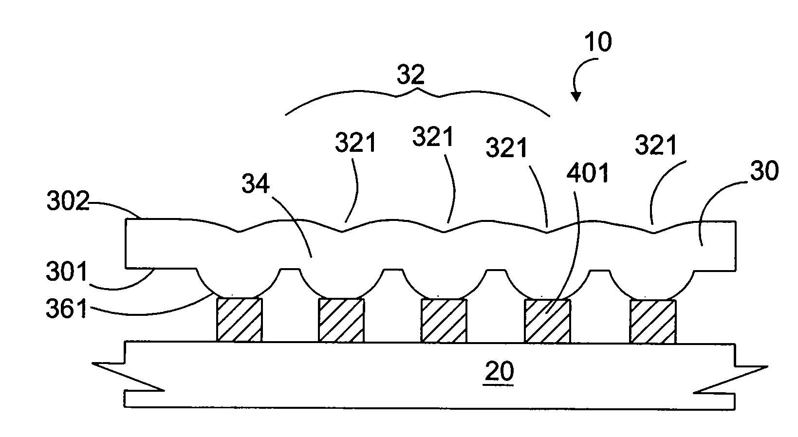
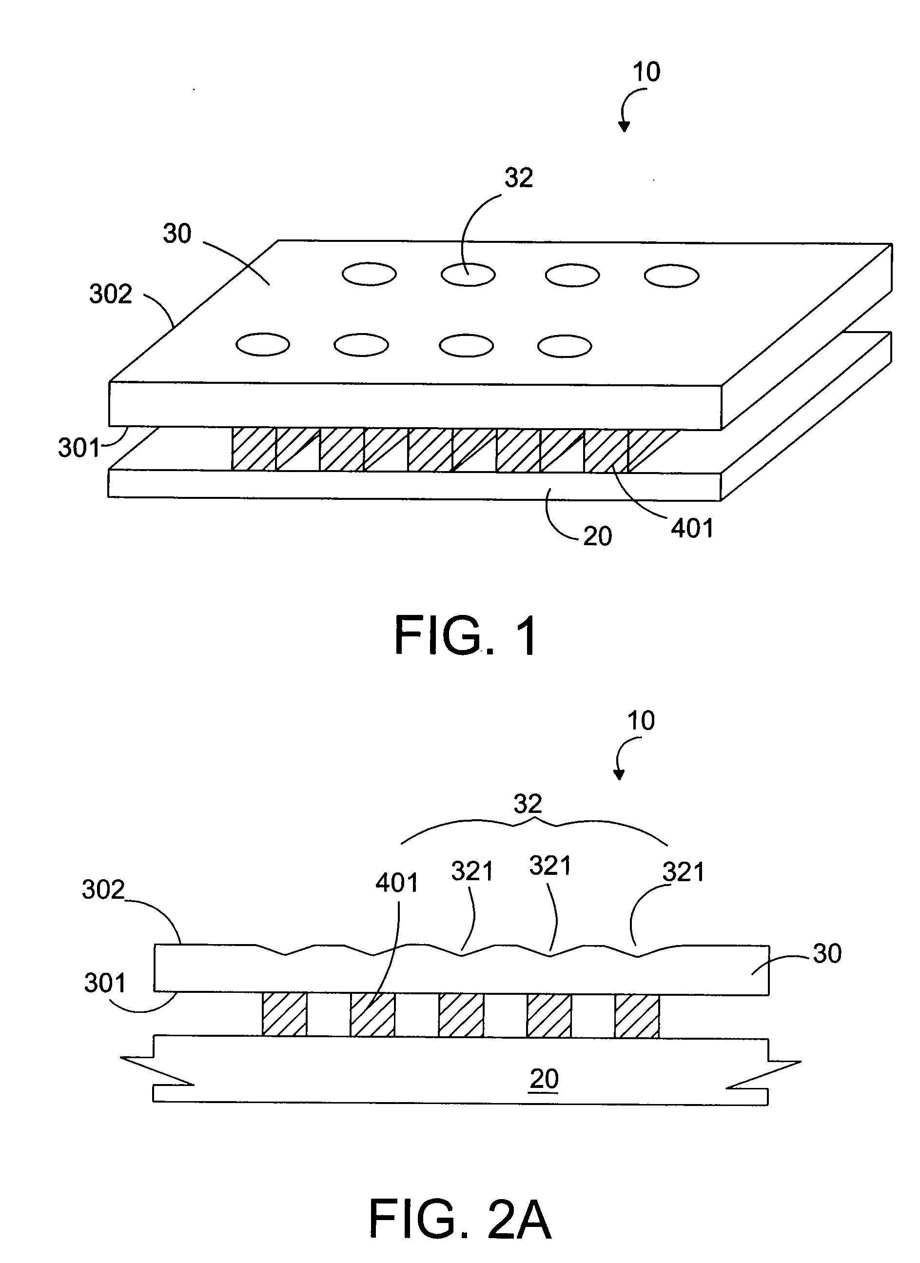
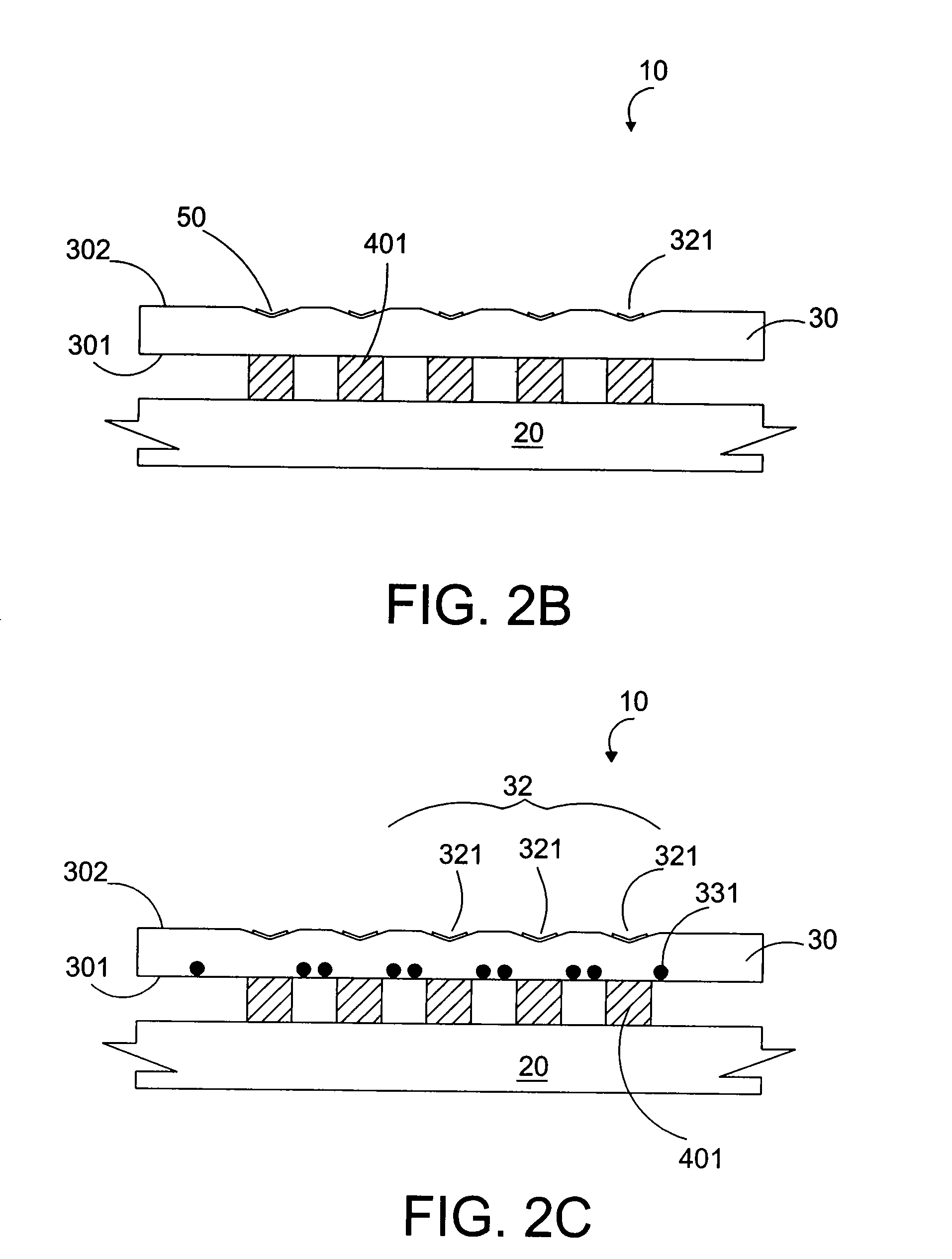
[0016]Referring to FIG. 1, a top view of a back light module having a direct type light guide plate according to the present invention is illustrated. The back light module 10 includes a printed circuit board 20, multiple light emitting diodes 401 and a light guide plate 30 having a light guide structure 32. The multiple light emitting diodes 401 may be disposed on the printed circuit board 20 as an array or in random to provide light with various required wavelengths. In this embodiment, the light guide structure 32 is arranged corresponding to multiple light emitting diodes 401. The multiple light emitting diodes 401 include multiple light emitting diode chips having...


PUM


Abstract

A backlight module including a printed circuit board, multiple light emitting diodes, and a light guide plate is disclosed. The multiple light emitting diodes can be arranged in an array or arbitrarily on the printed circuit board to provide the necessary light source for the back light module. The light guide plate with a light input surface and a light output surface is disposed on the multiple light emitting diodes. The light guide surface of the light guide plate may be flat or curved. A plurality of recesses on the light output surface of the light guide plate are configured to have the light from the light emitting diodes achieve total internal reflection effectively so that the lights are uniformly mixed in the light guide plate prior to emitting from the light guide plate. Therefore, light emitted from the light output surface of the light guide plate has higher brightness and more uniform energy.

Description

CROSS REFERENCE TO RELATED APPLICATIONS[0001]This application claims priority to Taiwan Patent Application Serial No. 95130636 entitled “BACK LIGHT MODULE WITH DIRECT TYPE LIGHT GUIDE PLATE AND LIGHTING DEVICE,” filed on Aug. 21, 2006.TECHNICAL FIELD[0002]The present invention relates to a back light module, and more particularly to a back light module with a direct type light guide plate, in which the structure of the light guide plate makes the light provided by light emitting devices achieve total internal reflection.BACKGROUND OF THE INVENTION[0003]Back light modules are conventionally edge type, in which the light is guided into the module from the edge of the light guide plate (LGP) to unify the light. However, in this way, the energy of the light with a large angle is not efficiently utilized, and the space for arranging light sources is limited to the edge of the module. Consequently, the brightness of the back light module is limited.[0004]As techniques of the liquid crysta...

Claims


Application Information

Patent Timeline
Patent Type & Authority Applications(United States)
IPC IPC(8): F21V7/04F21V7/00
CPCG02F1/133606G02F1/133603
Inventor CHIANG, CHENG-TING
Owner ONION TECH CORP
Why Eureka
Try Eureka