Preconnectorized fiber optic cable assembly

a technology of pre-connectorized fiber optic cables and distribution cables, applied in the direction of optics, fibre mechanical structures, instruments, etc., can solve the problems of certain challenges of pre-connectorized distribution cables in fiber optic communications networks, and achieve the effect of convenient and space-saving storage and high tensile load

Inactive Publication Date: 2008-07-24
CORNING CABLE SYST LLC
View PDF27 Cites 94 Cited by
  • Summary
  • Abstract
  • Description
  • Claims
  • Application Information

AI Technical Summary

Benefits of technology

[0006]To achieve the foregoing and other objects, and in accordance with the purposes of the invention as broadly described herein, the present invention provides various embodiments of a cable assembly for a preconnectorized distribution cable configured to be deployed in a fiber optic communications network. The distribution cable has a terminated end and a pulling grip assembly at the upstream end of the cable assembly. The pulling grip assembly is capable of transferring a high tensile load to the distribution cable without inducing relative movement between the cable elements. In the var

Problems solved by technology

However, the use of preconnectorized distribution cables in a

Method used


Image

  • Preconnectorized fiber optic cable assembly
  • Preconnectorized fiber optic cable assembly
  • Preconnectorized fiber optic cable assembly

Examples


Embodiment Construction

[0026]Reference will now be made to various embodiments of the invention, examples of which are illustrated in the accompanying drawings figures. Whenever possible, the same reference numerals are used throughout the drawing figures to refer to the same or like parts.

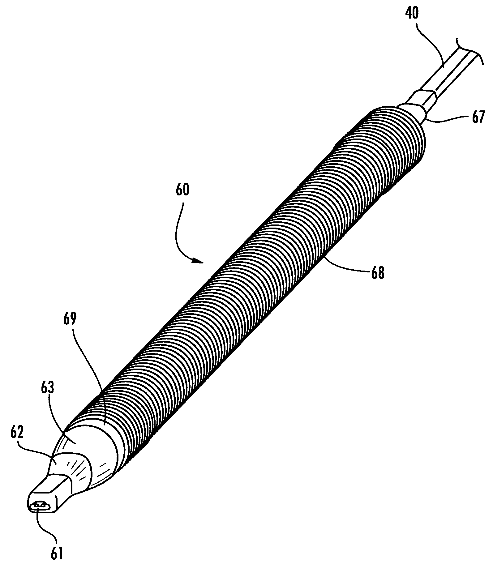
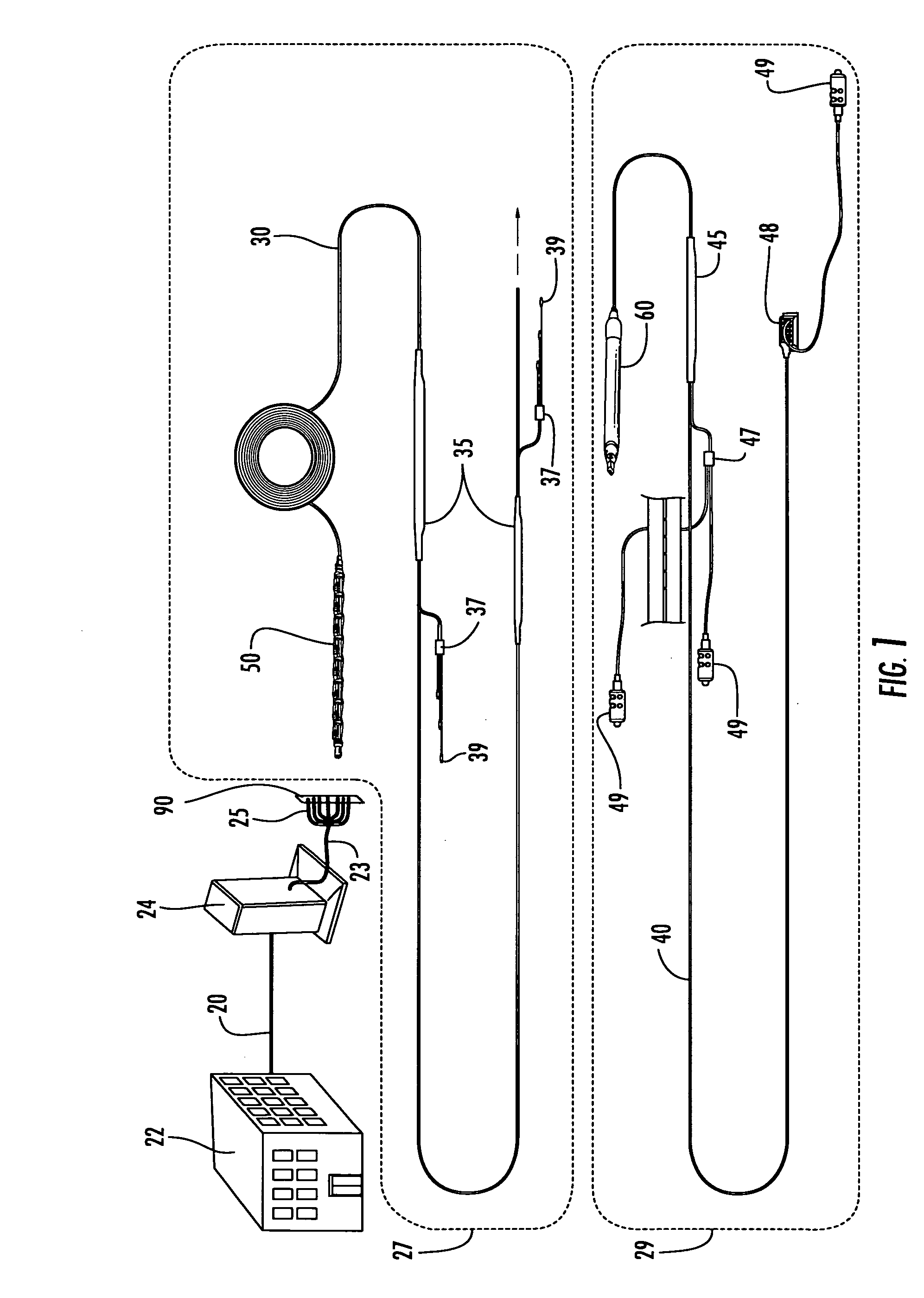
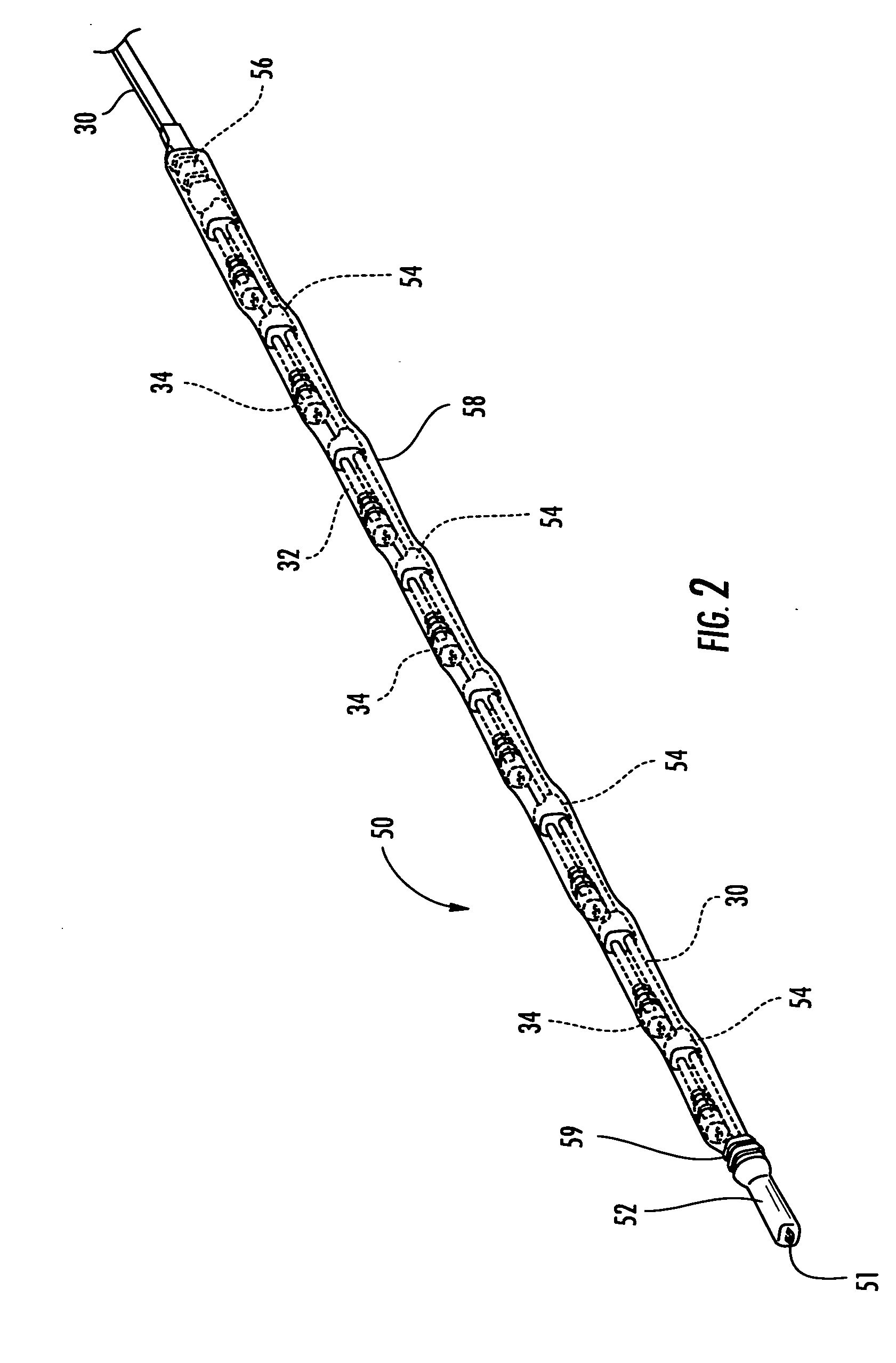
[0027]FIG. 1 illustrates a portion of a fiber optic network including a first cable assembly 27 according to the present invention and a second cable assembly 29 according to the present invention. As previously discussed, a feeder cable 20 interconnects a communications central office (CO) 22 with a fiber distribution hub (FDH) 24 in a conventional manner. The first cable assembly 27 includes a primary distribution cable 30 that interconnects the FDH 24 with a secondary distribution cable 40 of the second cable assembly 29. The FDH 24 distributes (e.g., splits) the relatively high power optical signals carried on the optical fibers of the feeder cable 20 into multiple lower power optical signals carried on a plurality ...


PUM


Abstract

A cable assembly configured to be deployed in a fiber optic communications network includes a pulling grip body disposed at an upstream end of the cable assembly and a preconnectorized distribution cable having a plurality of optical fibers and at least one strength member. The pulling grip body includes a pulling loop that is mechanically coupled to the strength member to permit a high tensile load to be transferred to the distribution cable without inducing relative movement between the cable elements. The pulling grip body is preferably formed by overmolding the pulling loop and the strength member with a flexible encapsulant material. At least one multifiber connector is terminated to optical fibers of the distribution cable at the upstream end. The pulling grip assembly and the preconnectorized distribution cable have a low profile capable of being pulled through a conduit.

Description

FIELD OF THE INVENTION[0001]The present invention relates to a cable assembly, and more particularly, to a cable assembly for a preconnectorized optical ribbon distribution cable configured to be deployed in a fiber optic communications network.BACKGROUND OF THE INVENTION[0002]Optical fiber is increasingly being used to deliver broadband communications, including voice, video and data transmissions, to subscribers over a fiber optic network. Such fiber optic communications networks require a number of connection terminals at which multiple optical fibers are interconnected. Examples of connection terminals include, but are not limited to, optical device enclosures, network access point (NAP) enclosures, aerial closures, below grade closures, pedestals, optical network terminals (ONTs) and network interface devices (NIDs). As illustrated in FIG. 1, a feeder cable 20 having a relatively low number of optical fibers typically interconnects a communications central office (CO) 22 and a ...

Claims


Application Information

Patent Timeline
IPC IPC(8): G02B6/44
CPCG02B6/4475G02B6/4473
Inventor KNECHT, DENNIS MICHAELLEWALLEN, CHRISTOPHER PAULLUTHER, JAMES PHILLIP
Owner CORNING CABLE SYST LLC
Why Eureka
Try Eureka