
Air conditioning apparatus and passage control device with slide resistance generating part

a technology of air conditioning apparatus and passage control device, which is applied in the direction of lighting and heating apparatus, heating types, transportation and packaging, etc., can solve the problems of maintaining the effect of slide resistance for a long time, and the rotational speed of the door increases, and the sealing effect of the door is effectively maintained

Inactive Publication Date: 2008-07-24
DENSO CORP
View PDF0 Cites 17 Cited by
  • Summary
  • Abstract
  • Description
  • Claims
  • Application Information

AI Technical Summary

Benefits of technology

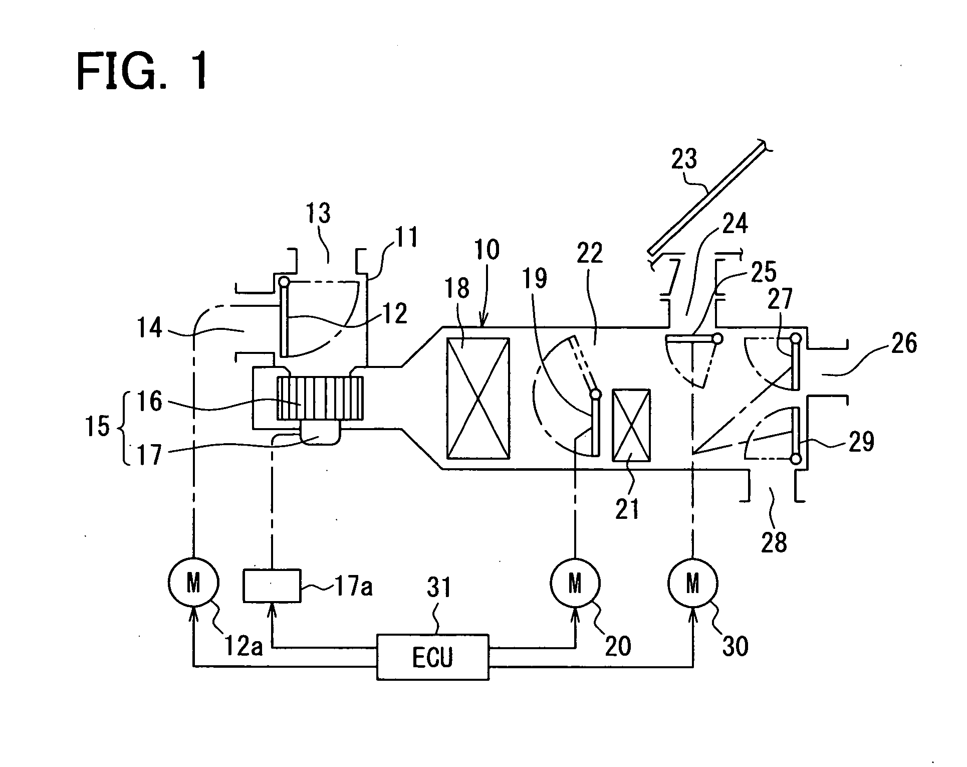
[0011]Accordingly, a predetermined slide resistance is generated by the viscous fluid when the rotatable member rotates. Further, it is configured such that the resistance increases as a rotational speed of the rotatable member increases. Therefore, self-induced vibration, which is generally rapid movement, of the rotatable member is reduced. Due to the effect of the slide resistance, it is less likely that the rotatable member will generate noise When moving even under a low temperature. Also, a sealing effect of the rotatable member is effectively maintained. Since the viscous fluid is enclosed in the closed space, the resistance is effectively generated. Moreover, deterioration of the viscous fluid is reduced. Thus, the effect of the slide resistance is maintained for a long time.
[0013]The rotatable member is, for example, one of a door that is rotatable disposed to open and close the passage and a link member that is coupled to the door for transmitting the rotational force. It is configured such that the resistance increases as a rotational speed of the door increases. Therefore, self-induced vibration, which is generally rapid movement, of the door is reduced. Due to the effect of the slide resistance, it is less likely that the door will generate noise when moving even under a low temperature. Also, a sealing effect of the door is effectively maintained. Since the viscous fluid is enclosed in the closed space, the resistance is effectively generated. Moreover, deterioration of the viscous fluid is reduced. Thus, the effect of the slide resistance is maintained for a long time.

Problems solved by technology

Thus, the effect of the slide resistance is maintained for a long time.

Method used


Image

  • Air conditioning apparatus and passage control device with slide resistance generating part
  • Air conditioning apparatus and passage control device with slide resistance generating part
  • Air conditioning apparatus and passage control device with slide resistance generating part

Examples


seventh embodiment

[0101]Referring to FIGS. 8 and 9, in the seventh embodiment, the slide resistance generating part is exemplarily employed to a bearing part of a link plate 34A of the air mix door linking device (e.g., door link part). The link plate 34A is coupled to the air mix door 19 through a lever plate 32D for transmitting a rotational force to the air mix door 19. Here, the link plate 34A serves as the rotational member.

[0102]The shaft 191 of the air mix door 19 passes through the shaft hole 101 of the air conditioning case 10. The lever plate 32D is engaged with the end of the shaft 191, and extends in a predetermined direction through a positioning mechanism (not shown). The lever plate 32D is formed with a link opening L1 to be connected to a first link pin P2 of a first end of the link plate 34A.

[0103]The driving device 20 is, for example, a servomotor, and has a driving shaft 20a. The driving shaft 20a is coupled to a driving-side lever plate 33. The lever plate 33 is formed with a link...

eighth embodiment

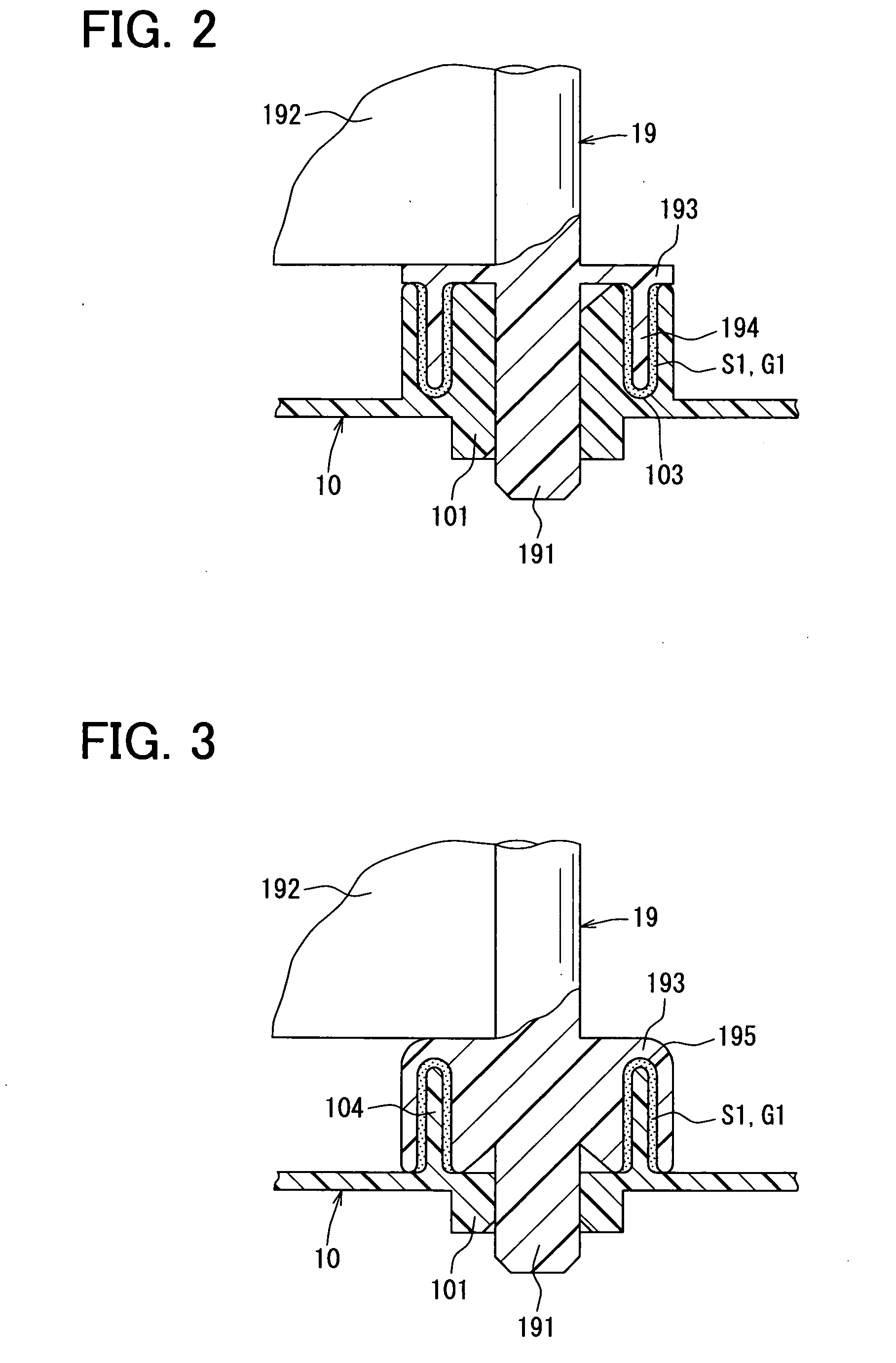
[0110]Referring to FIG. 10, in the eighth embodiment, the air mix door 19 has the expanded portion 193 having a flange-like or disc shape on a periphery of the shaft 191. The air mix door 19 further has the rotational projection 194 that projects from the axially outer surface of the expanded portion 193. The rotational projection 194 has the cylindrical shape and is coaxial with the shaft 191.

[0111]The air conditioning case 10 has the fixed projection 104 on the periphery of the shaft hole 101. The fixed projection 104 projects from the inner surface of the air conditioning case 10 toward the expanded portion 193. The fixed projection 104 has a cylindrical shape and has an inner diameter larger than an outer diameter of the rotational projection 194. The rotational projection 194 is received in the space defined by the cylindrical fixed projection 104 such that an outer circumferential surface of the rotational projection 194 is opposed to an inner circumferential surface of the fi...

ninth embodiment

[0115]Referring to FIG. 11, in the ninth embodiment, the relationship between the rotational projection 194 and the fixed projection 104 is reversed from that of the eighth embodiment shown in FIG. 10. The rotational projection 194 is located on an outer circumferential side of the fixed projection 104. The closed space S1 is provided between an inner circumferential surface of the rotational projection 194 and an outer circumferential surface of the fixed projection 104. The closed space S1 is filled with the high-viscosity grease G1 so as to generate the predetermined slide resistance when the air mix door 19 rotates.

[0116]Also in this structure, the closed space S1 that is filled with the high-viscosity grease G1 is provided between the opposed surfaces of the air conditioning case 10 and the air mix door 19. Thus, the effects of the slide resistance will be provided, similar to the above embodiments.


PUM


Abstract

An air conditioning apparatus has a case and a rotatable member that is rotatably supported by the case. The rotatable member and the case define a closed space between opposed surfaces thereof. The closed space is filled with a high-viscosity fluid having a predetermined coefficient of viscosity so as to generate a predetermined resistance to move of the rotatable member. The rotatable member is, for example, a door and a member of a link mechanism that operates the door, such as a lever plate, a link plate or the like.

Description

CROSS REFERENCE TO RELATED APPLICATION[0001]This application is based on Japanese Patent Applications No. 2007-10697 filed on Jan. 19, 2007 and No. 2007-287684 filed on Nov. 5, 2007, the disclosures of which are incorporated herein by reference.FIELD OF THE INVENTION[0002]The present invention relates to an air conditioning apparatus having a rotatable member, such as a door for controlling a passage.BACKGROUND OF THE INVENTION[0003]An air conditioning apparatus for a vehicle has a door device, such as an air mix door, for opening and closing a passage defined in an air conditioning case. For example, the air mix door having a substantially plate shape is rotatably supported in a case at a position upstream of a heater core. In a maximum heating mode, the air mix door is moved to a position at which an opening of a cooled air passage through which air cooled by an evaporator flows while bypassing the heater core is closed. In a maximum cooling mode, the air mix door is moved to a po...

Claims


Application Information

Patent Timeline
Patent Type & Authority Applications(United States)
IPC IPC(8): B60H1/26
CPCB60H1/00671F24F13/1486B60H2001/00707
Inventor HASHIMOTO, SHIHO
Owner DENSO CORP
Learn More