System and Method for Temporary Protection Operation of a Controller Box for a Railroad Switch Turnout

a controller box and turnout technology, applied in the field of operation of railroad signaling systems, can solve the problems of unreliable and unrated electronic proximity sensors, inability to facilitate non-power applications of such railroad switches, and high cost of electronic proximity sensors, so as to facilitate shunting

Active Publication Date: 2008-07-31
GENERAL ELECTRIC CO
View PDF5 Cites 12 Cited by
  • Summary
  • Abstract
  • Description
  • Claims
  • Application Information

AI Technical Summary

Benefits of technology

[0006]In another embodiment of the present invention, a system is provided for temporary protection operation of a controller box for a railroad switch turnout in a non-powered mode. The railroad switch turnout includes a normal and a reverse switch point positioned between respective normal and reverse stationary stock rails and a pair of movable switch rails disposed between the stationary stock rails. The normal and reverse switch points are movable between a normal position and a reverse position. The system includes a normal controller box coupled to the normal switch point to move the normal switch point between the normal position and the reverse position. Each normal controller box includes a housing, at least one block slidably received within the housing based upon moving the normal switch point to establish at least one pair of electrical contacts within the housing. Each pair of electrical contacts include at least one pair of compressed contacts indicative of moving the normal switch point into the normal position and at least one pair of extended contacts indicative of moving the normal switch point out of the normal position. The normal controller box further includes a pair of rail connections coupling each pair of electrical contacts to a respective normal and reverse stationary stock rail. Upon establishing each pair of compressed contacts, the pair of rail connections and pair of compressed contacts facilitate respective opposing current along the normal and reverse stationary stock rails indicative of a safe condition of the railroad switch turnout. Upon establishing each pair of extended contacts, the pair of rail connections and pair of extended contacts facilitate shunting of the respective normal and reverse stationary stock rails indicative of an unsafe condition of the railroad switch turnout.

Problems solved by technology

However, such electronic proximity sensors are costly, unreliable and not rated in extreme environmental temperature fluctuations.
Additionally, these electronic proximity sensors do not facilitate non-power applications of such railroad switches, aka the passing through of track circuit indication or the shunting of the same track circuit indication.

Method used


Image

  • System and Method for Temporary Protection Operation of a Controller Box for a Railroad Switch Turnout
  • System and Method for Temporary Protection Operation of a Controller Box for a Railroad Switch Turnout
  • System and Method for Temporary Protection Operation of a Controller Box for a Railroad Switch Turnout

Examples


Embodiment Construction

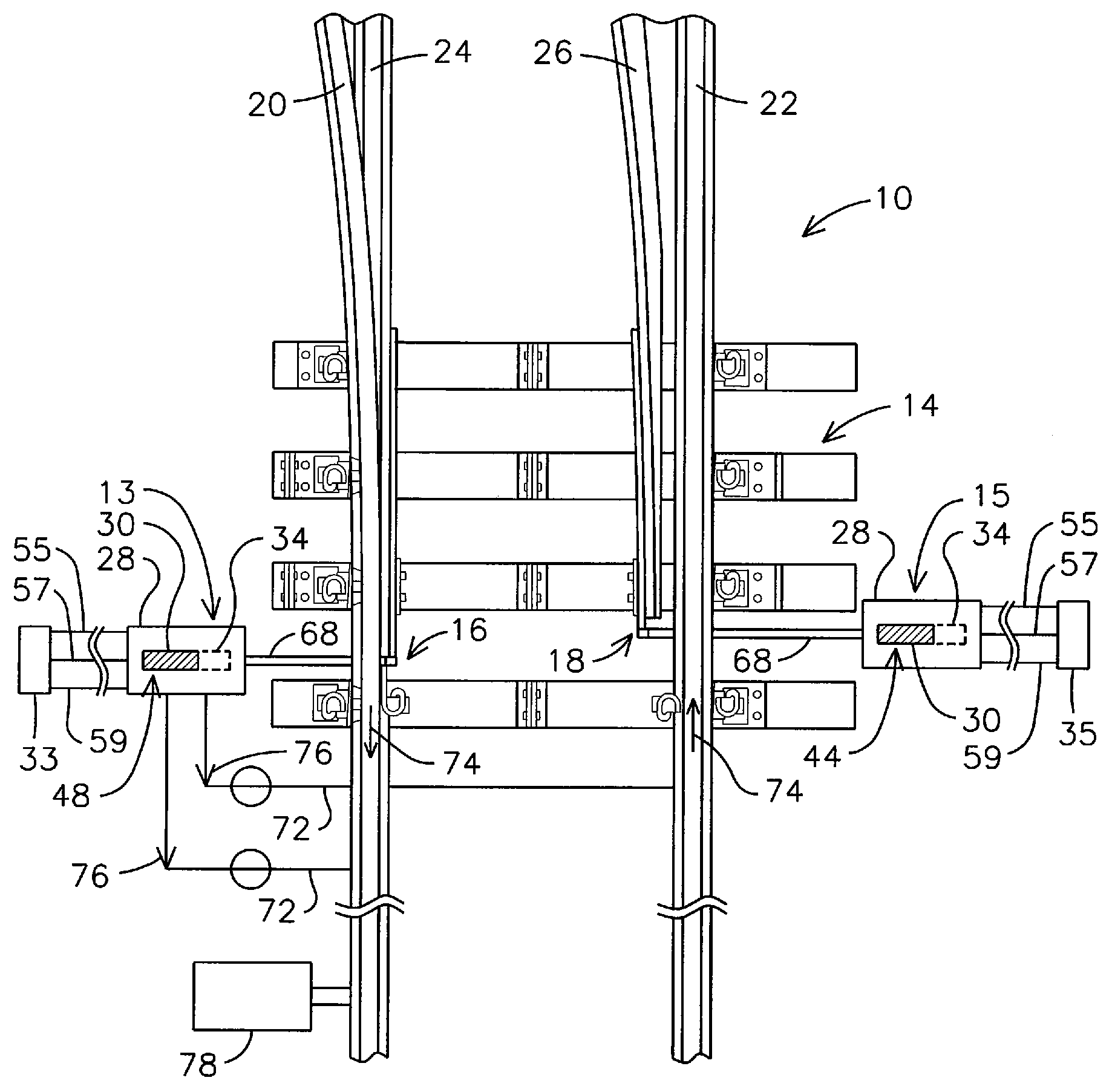
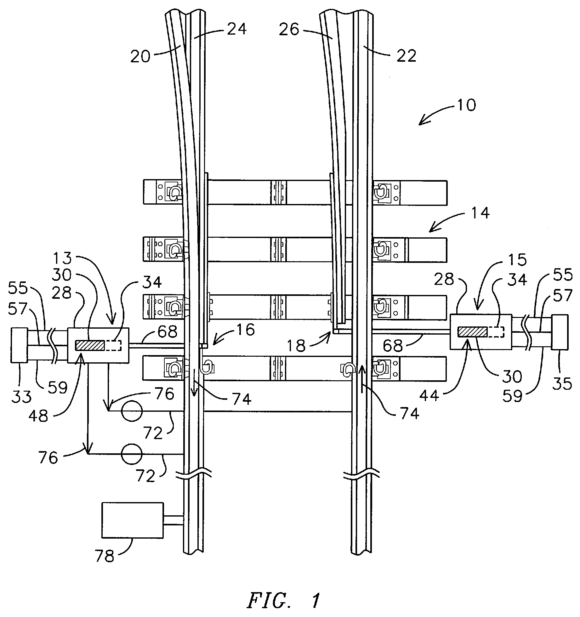
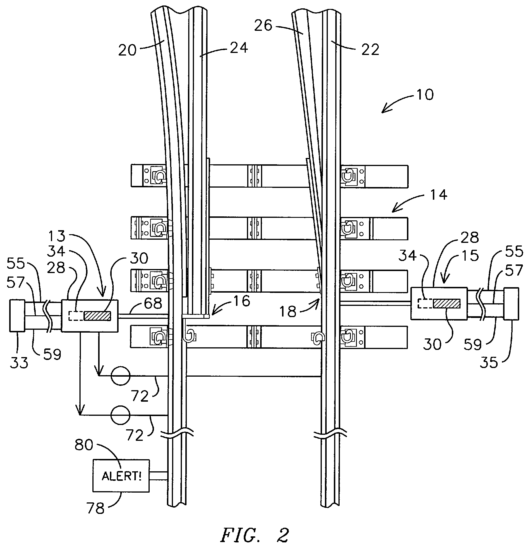
[0020]FIG. 1 illustrates an embodiment of a system 10 for providing temporary protection operation to a normal controller box 13 and reverse controller box 15 of a railroad switch turnout 14 in a powered mode. The railroad switch turnout 14 illustratively includes a normal and a reverse switch point 16,18 positioned between respective normal and reverse stationary stock rails 20,22 and a pair of movable switch rails 24,26 disposed between the stationary stock rails. The normal and reverse switch points 16,18 are movable between a normal position (FIG. 1) and a reverse position (FIG. 2).

[0021]As illustrated in FIGS. 1 and 2, the system 10 includes a normal controller box 13 coupled to the normal switch point 16 to move the normal switch point between the normal position (FIG. 1) and out of the normal position, such as into the reverse position, for example (FIG. 2). The system 10 further includes a_reverse controller box 15 coupled to the reverse switch point 18 to move the reverse s...


PUM


Abstract

A system is provided for temporary protection operation of at least one controller box for a railroad switch turnout in a powered mode or non-power mode depending on the railroad configuration and independent of the controller box. A normal controller box is coupled to the normal switch point and includes a block slidably received within the housing based on moving the normal switch point to establish at least one pair of electrical contacts within the housing. A controller is coupled to the controller box to verify a pair of compressed contacts to determine that the normal switch point has moved to the normal position to cause the controller box to send an open signal to a pair of switch connections. The controller also verifies a pair of extended contacts to determine that the normal switch point has failed to move to the normal position to omit to cause said controller box to send an open signal to the pair of switch connections and maintain each respective switch connection to shunt the stationary stock rails.

Description

FIELD OF THE INVENTION[0001]The present invention relates to the operation of railroad signaling systems, and more particularly, to a system, method and microprocessor readable media for temporary protection operation of a controller box for a railroad switch turnout.BACKGROUND OF THE INVENTION[0002]In order to optionally switch a railroad train operating on a first track to a second, merging track, it is typical to provide a railroad switch with a pair of switch points which are selectively movable horizontally to deflect the train toward one or the other of the tracks. The railroad switch can encompass a pair of movable switch rail lengths which extend several feet in length with the switch points. The switch points, typically labeled as “normal” and “reverse”, are selectively movable back and forth between a pair of stock rails between a normal position in which a normal stock rail is positioned against a respective movable switch rail and a reverse position in which a reverse st...

Claims


Application Information

Patent Timeline
Patent Type & Authority Applications(United States)
IPC IPC(8): B61L5/00
CPCB61L5/107B61L1/18
Inventor WAGNER, DON R.FEAR, HAROLD L.
Owner GENERAL ELECTRIC CO
Why Eureka
Try Eureka