Integrated and self-contained suspension assembly having an on-the-fly adjustable air spring

Inactive Publication Date: 2008-07-31
FOX FACTORY
View PDF17 Cites 25 Cited by
  • Summary
  • Abstract
  • Description
  • Claims
  • Application Information

AI Technical Summary

Benefits of technology

[0010]One aspect of a preferred embodiment is to provide a suspension air spring, optionally integrated with a shock absorber or other damper, that permits instant selection between “soft” and “firm” spring rate curves by simply turning an external knob one-quarter turn. This is much quicker and easier than other methods provided by conventional prior-art designs. The illustrated embodiments are particularly applicable to bicycles.
[0011]In the context of real-world mountain biking, all prior-art methods of changing air spring rates create a significant interruption in the ride, and thus typically are done infrequently, or not at all, during a ride. In contrast, turning an external knob as described according to a preferred embodiment is so quick and simple that it can be done in a routine “on-the-fly” manner dozens of times as desired during a typical ride. Since terrain and trail conditions constantly change, this greatly benefits the rider by enabling him / her to continuously select the best spring rate for the current situation.
[0013]When the check ball is seated, the passage is closed and air flow from the first partial volume to the second partial volume is blocked. This isolates the second partial volume and prevents it from physically participating as a part of the air spring upon compression of the suspension. As is well-known in the art, air spring characteristics depend upon the initial pressure and volume characteristics of the air spring. When the total initial volume is effectively reduced, as occurs here when the passage leading to the second partial volume is blocked, the air spring characteristic (“spring curve”) becomes firmer.
[0014]When the check ball is unseated, the passage is open and air flow between the two partial volumes is unrestricted. This, of course, makes both partial volumes physically available to the air spring, and results in greater total initial volume and a softer air spring characteristic.
[0016]Another preferred embodiment is a gas spring assembly including a body portion and a shaft portion. The shaft portion is telescopingly engaged with the body portion. A piston is carried by the shaft portion and cooperates with the body portion to define a variable volume first gas chamber. One of the shaft portion and the body portion at least partially defines a second gas chamber. A valve assembly is positionable in a first position and a second position. In the first position, the valve assembly substantially prevents communication between the first gas chamber and the second gas chamber and in the second position, the valve assembly permits communication between the first gas chamber and the second gas chamber.
[0017]Another aspect of the present invention involves a front suspension fork assembly positionable on a bicycle. The front fork assembly includes a gas spring assembly having a body portion and a shaft portion. The shaft portion is telescopingly engaged with the body portion. A piston is carried by the shaft portion and cooperates with the body portion to define a variable volume first gas chamber. One of the shaft portion and the body portion at least partially defines a second gas chamber. A valve assembly is positionable in a first position and a second position. In the first position, the valve assembly substantially prevents communication between the first gas chamber and the second gas chamber and in the second position, the valve assembly permits communication between the first gas chamber and the second gas chamber. The valve assembly is movable between the first position and the second position by an actuator positioned to be accessible to a hand of a rider of the bicycle while riding.

Problems solved by technology

In the context of real-world mountain biking, all prior-art methods of changing air spring rates create a significant interruption in the ride, and thus typically are done infrequently, or not at all, during a ride.

Method used


Image

  • Integrated and self-contained suspension assembly having an on-the-fly adjustable air spring
  • Integrated and self-contained suspension assembly having an on-the-fly adjustable air spring
  • Integrated and self-contained suspension assembly having an on-the-fly adjustable air spring

Examples


Embodiment Construction

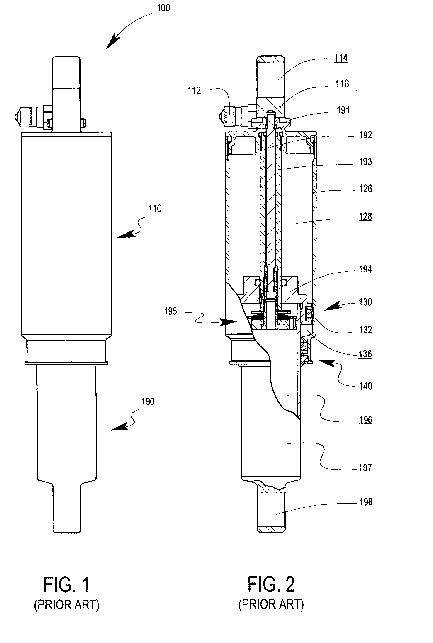
[0034]The prior-art integrated suspension unit 100 of FIGS. 1 and 2 will be described first, in order to provide a point of departure for better understanding the improvements of the preferred embodiments, which will be described further on.

[0035]The typical prior-art integrated suspension unit 100 as shown in FIGS. 1 and 2 is manufactured by Fox Racing Shox. It is to be understood, of course, that this specific prior-art embodiment is representative only, and that the present air spring arrangement can be applied to other types of suspension units. Additionally, the present air spring arrangement can be applied as a separate air spring unit, not integrated with a damper.

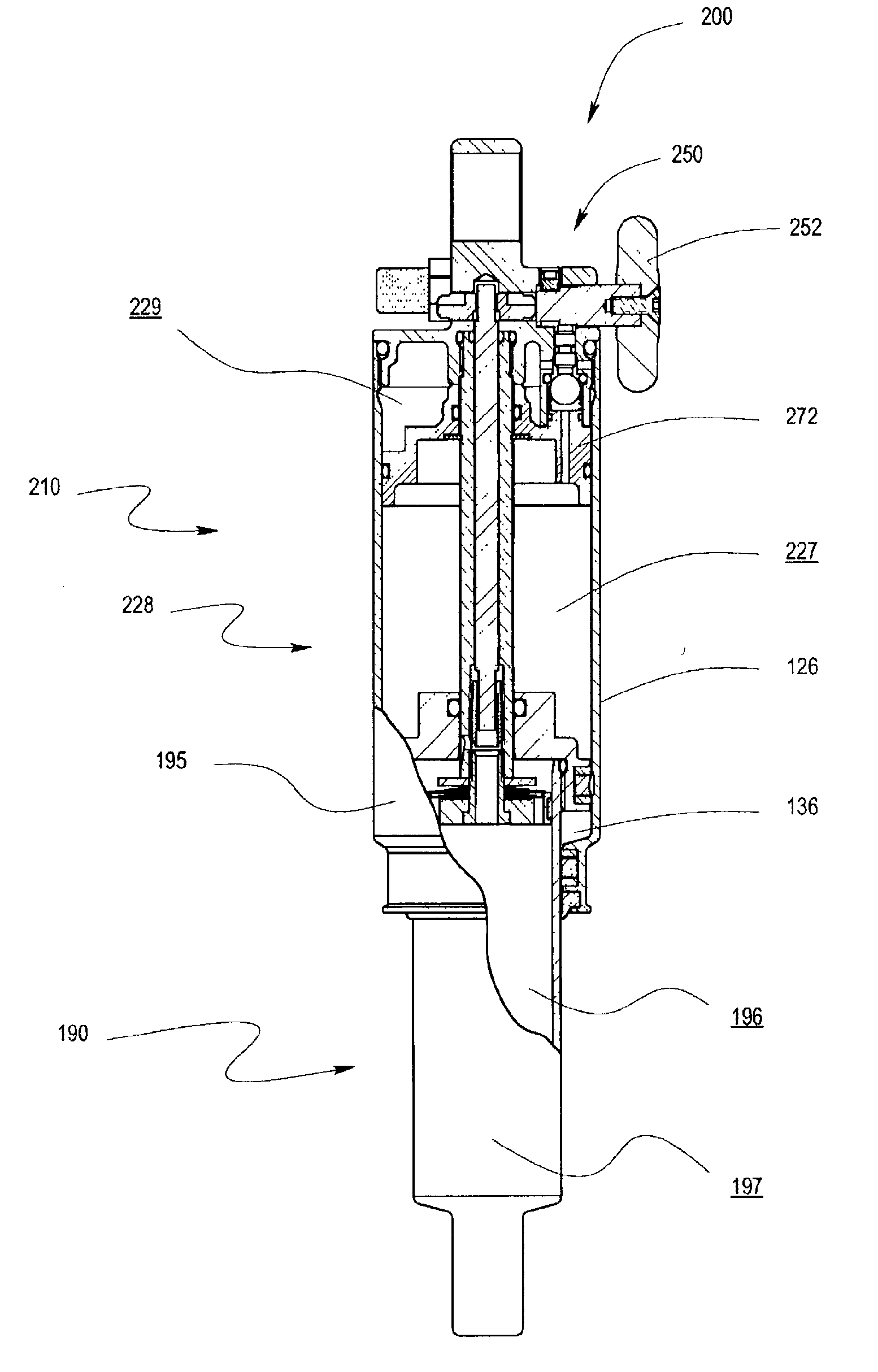
[0036]In FIGS. 1 and 2 the integrated suspension unit 100 is comprised of an air spring assembly 110 and a damper assembly 190. The integration is seamless, with several of the components such as an upper eyelet housing 116 and seal head 194 shared by both assemblies and performing dual functional roles. For example...


PUM


Abstract

An integrated and self-contained suspension assembly having a gas spring integrated with a shock absorber (damper) is described. The rigid gas cylinder of the air spring is divided into a first gas chamber and a second gas chamber. A flow port connects the first and second gas chambers, and can be manually opened or closed by valve and a simple one-quarter turn rotation of an external knob to instantly switch the gas spring between two different spring rates. The different spring rates are functions of the separate or combined volumes of the two gas chambers. The integrated suspension assembly is compactly packaged and self-contained, i.e., does not require any externalities, such as gas sources or electricity, to operate.

Description

BACKGROUND OF THE INVENTION[0001]1. Field of the Invention[0002]A preferred embodiment relates to air springs for vehicle suspensions and preferably two-wheeled vehicle suspensions, such as the suspensions of bicycles, which are typically mounted between the chassis of the vehicle and a wheel. In particular, a preferred embodiment relates to an air spring, optionally combined with a shock absorber or other damper to form an integrated suspension unit, which permits instant selection between two different spring rate curves by simply rotating an external knob one-quarter turn.[0003]2. Description of the Related Art[0004]One advantage of air springs is the ability to change spring rate (“softer” or “stiffer”) simply by adjusting the internal air pressure. Such a method permits changing the spring rate curve of an air spring, and is available for essentially all air springs. On many air springs this is accomplished relatively easily by pressurizing or de-pressurizing the air spring wit...

Claims


Application Information

Patent Timeline
Patent Type & Authority Applications(United States)
IPC IPC(8): F16F9/02F16F9/44B62K25/04F16F9/06F16F9/46
CPCB62K25/04B62K2025/048F16F9/0209F16F9/06F16F13/002B60G15/12B60G17/0523B62K2201/08F16F9/46B60G2300/12B60G2500/20F16F9/0236F16F9/3257F16F9/461F16F2228/066
Inventor FOX, ROBERT C.
Owner FOX FACTORY
Why Eureka
Try Eureka