Pulse width modulation dimming control method and display apparatus having pulse width modulation dimming control function

a technology of pulse width modulation and control function, which is applied in the direction of pulse technique, electrical apparatus, instruments, etc., can solve the problems of generating luminance difference and gradation unbalance between horizontal lines on display panels, and achieve the effect of preventing luminance differen

Inactive Publication Date: 2008-07-31
SAMSUNG ELECTRONICS CO LTD
View PDF10 Cites 25 Cited by
  • Summary
  • Abstract
  • Description
  • Claims
  • Application Information

AI Technical Summary

Benefits of technology

[0011]The present invention provides a PWM dimming control method and a display apparatus having a PWM dimming control function for preventing a luminance difference and a gradation unbalance between horizontal lines on a display panel when an LED back light is operated in the group lighting back light mode.

Problems solved by technology

As described above, gate lines included in a predetermined block have different PWM periods, and thus a luminance difference and a gradation unbalance between horizontal lines on a display panel are generated.

Method used


Image

  • Pulse width modulation dimming control method and display apparatus having pulse width modulation dimming control function
  • Pulse width modulation dimming control method and display apparatus having pulse width modulation dimming control function
  • Pulse width modulation dimming control method and display apparatus having pulse width modulation dimming control function

Examples


Embodiment Construction

[0025]The present inventive concept will now be described more fully with reference to the accompanying drawings, in which exemplary embodiments of the invention are shown. The present inventive concept may, however, be embodied in many different forms and should not be construed as being limited to the exemplary embodiments set forth herein; rather, these exemplary embodiments are provided so that this disclosure will be thorough and complete, and will fully convey the concept of the invention to those skilled in the art. Throughout the drawings, like reference numerals refer to like elements.

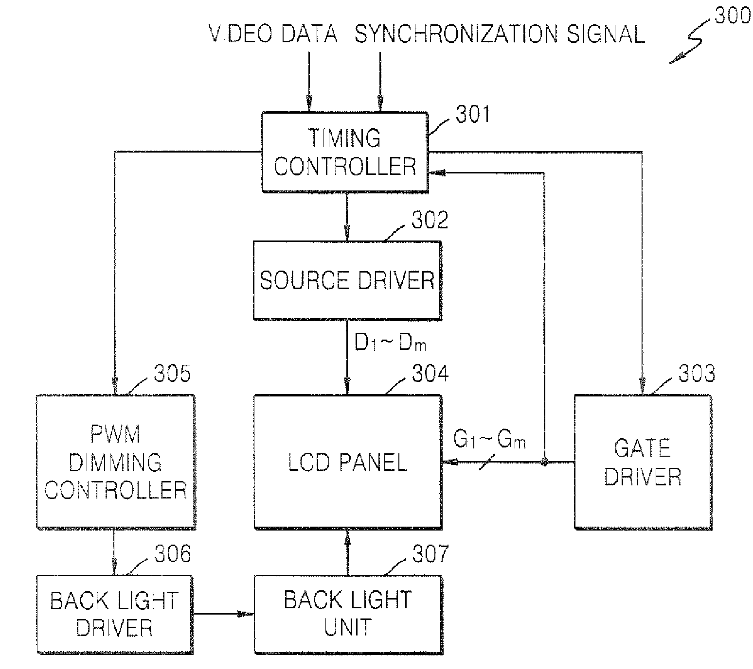
[0026]FIG. 3 is a block diagram of a display apparatus 300 according to an exemplary embodiment of the present invention. Referring to FIG. 3, the display apparatus 300 includes a timing controller 301, a source driver 302, a gate driver 303, an LCD panel 304, a PWM dimming controller 305, a back light driver 306, and a back light unit 307.

[0027]The timing controller 301 receives video data co...


PUM


Abstract

A pulse width modulation (PWM) dimming control method and a display apparatus having a PWM dimming control function are provided. The method includes setting a PWM period of a group lighting block based on a state of both a first gate line and a last gate line among a plurality of gate lines corresponding to the group lighting block; and controlling PWM dimming of the group lighting block based on the set PWM period. The display apparatus includes a timing controller which determines a pulse width modulation (PWM) period of a group lighting block based on a state of both a first gate line and a last gate line among a plurality of gate lines corresponding to the group lighting block; and a PWM dimming controller which generates a PWM signal for controlling PWM dimming based on the determined PWM period.

Description

CROSS-REFERENCE TO RELATED PATENT APPLICATION[0001]This application claims priority from Korean Patent Application No. 10-2007-0007942, filed on Jan. 25, 2007, in the Korean Intellectual Property Office, the disclosure of which is incorporated herein in its entirety by reference.BACKGROUND OF THE INVENTION[0002]1. Field of the Invention[0003]Methods and apparatuses consistent with the present invention relate to a pulse width modulation (PWM) dimming control, and more particularly, to PWM dimming control using a light-emitting diode (LED) back light unit.[0004]2. Description of the Related Art[0005]An LED back light unit is a device that illuminates a display panel such as a thin film transistor-liquid crystal display (TFT-LCD) panel using an LED as a light source. The TFT-LCD panel is a light-receiving display device that forms images using external light, and thus the TFT-LCD panel uses a fluorescent lamp for irradiating the backside thereof. The LED back light unit functions as t...

Claims


Application Information

Patent Timeline
Patent Type & Authority Applications(United States)
IPC IPC(8): G09G3/36H03K7/08
CPCG09G3/342G09G3/3648G09G2310/024G09G2320/0646G09G2320/0233G09G2320/064G09G2310/08
Inventor JEONG, JIN-GILYANG, JOON-HYUNPANKAJ, AGARWAL
Owner SAMSUNG ELECTRONICS CO LTD
Why Eureka
Try Eureka