Object storage device having shaking function

a storage device and function technology, applied in the field of objects storage devices having shaking functions, can solve the problems of not allowing shake-proof locking of objects, falling out of retainers, and difficult integration of shaking functions, and achieves simple operation, high functional reliability, and easy automatic loading and unloading of objects.

Inactive Publication Date: 2008-07-31
THERMO ELECTRONICS LED GMBH
View PDF7 Cites 8 Cited by
  • Summary
  • Abstract
  • Description
  • Claims
  • Application Information

AI Technical Summary

Benefits of technology

[0005]The object of the present invention is thus to improve the handling and operation of an object storage device having multiple object storage points situated one on top of another, in particular in regard to uniform and reproducible shaking of all objects situated in the storage cassette.
[0006]The object is achieved for an object storage device having a shaking function having a vertically situated storage cassette, which has multiple object storage points situated one on top of another, and having a drive unit functionally connected to the storage cassette via a first drive connection, comprising a drive element for performing a shaking movement of the storage cassette, in that it has a further functional connection of the drive unit to the storage cassette via a second drive connection, the first drive connection being connected to a floor area of the storage cassette and the second drive connection being connected to a head area of the storage cassette, and a control unit is provided, which is implemented to synchronize the two drive connections. An essential basic idea of the present invention is thus to integrate multiple drive connections for the functional connection of the drive unit to the storage cassette in the object storage device. A functional connection in the meaning of the present invention is particularly to be understood as a connection for transmitting drive power generated by the drive element, such as a motor, for shaking to the storage cassette. This may occur via a direct connection, for example, via a gear, or, for example, also via magnetic interactions which are triggered via the drive unit and are transmitted to the storage cassette in the area of the drive connection. Accordingly, a drive unit comprises at least one drive element and possibly, for example, gear elements, etc., which are used to transmit the drive power exerted by the drive element to trigger the shaking movement of the storage cassette. According to the present invention, the first and second drive connections are connected to the storage cassette spatially separate from one another. For this purpose, it is advantageous to space apart the engagement points of the first and second drive connections as far as possible from one another. In this way, it is possible to transmit the shaking movement of the storage cassette not only on one side, but rather on multiple sides, and in particular on two sides to the storage cassette. An especially uniform shaking movement which is homogeneous over the entire storage cassette is thus executed. A further essential basic idea of the present invention is the synchronization of the first and second drive connections. This synchronization of the movements of the first and second drive connections ensures that the storage cassette is shaken uniformly over its entire longitudinal axis and allows a torsion-free shaking movement of the storage cassette. It is therefore possible to achieve especially good, reproducible shaking results using an object storage device according to the present invention, so that also storage cassettes having more than 10 and particularly more than 15 object storage points situated one on top of another may be shaken reliably and uniformly over the entire storage area and in particular over the entire longitudinal extension of the storage cassette.
[0007]The first and second drive connections preferably lie opposite to one another in relation to the storage cassette, the first drive connection being functionally connected from below and the second drive connection being functionally connected from above and especially preferably at diametrically opposite border areas to the at least one storage cassette. A connection of the first drive connection in the vertical direction of the storage cassette to the upper head area of the storage cassette and of the second connection to the lower floor area of the storage cassette is thus especially preferred. A connection of this type of the first and second drive connections to the front faces along the longitudinal axis of the storage cassette is particularly advantageous, because in this way an especially uniform shaking movement which is homogeneous over the entire length of the storage cassette may be ensured particularly well.

Problems solved by technology

The integration of a shaking function proves difficult here, however, because in this object storage device the objects introduced into the inserts are stored loosely in the object storage points and thus may fall out of the retainers due to a shaking movement of the storage cassette.
However, these do not allow shake-proof locking of the object, but rather are exclusively used to ensure an object is inserted completely into an object storage point.
The use of retention angles is precluded for an object storage device having multiple object storage points situated one on top of another, however, because introducing the objects from above is disadvantageous due to of the increased space demand, for example.
However, this attempted solution also requires the introduction of the objects into the object storage point from above, so that this device is only poorly suitable for storing and shaking larger numbers of objects and / or larger storage cassettes having multiple object storage points lying one on top of another.
In addition, ensuring uniform distribution of the shaking movement over the entire length of the storage cassette is problematic in the development of object storage devices having multiple and in particular more than 10 object storage points per cassette.
An uneven extent of the shaking movement in the individual object storage points is particularly problematic because the shaking results obtained are not uniform over the longitudinal axis of the storage cassette and are thus not reproducible.
The above-mentioned disadvantages arise particularly clearly in climatic cabinets having such object storage devices, in which multiple objects are stacked one on top of another.

Method used


Image

  • Object storage device having shaking function
  • Object storage device having shaking function
  • Object storage device having shaking function

Examples


Embodiment Construction

[0036]In the embodiments illustrated in the following, identical components are provided with identical reference numerals.

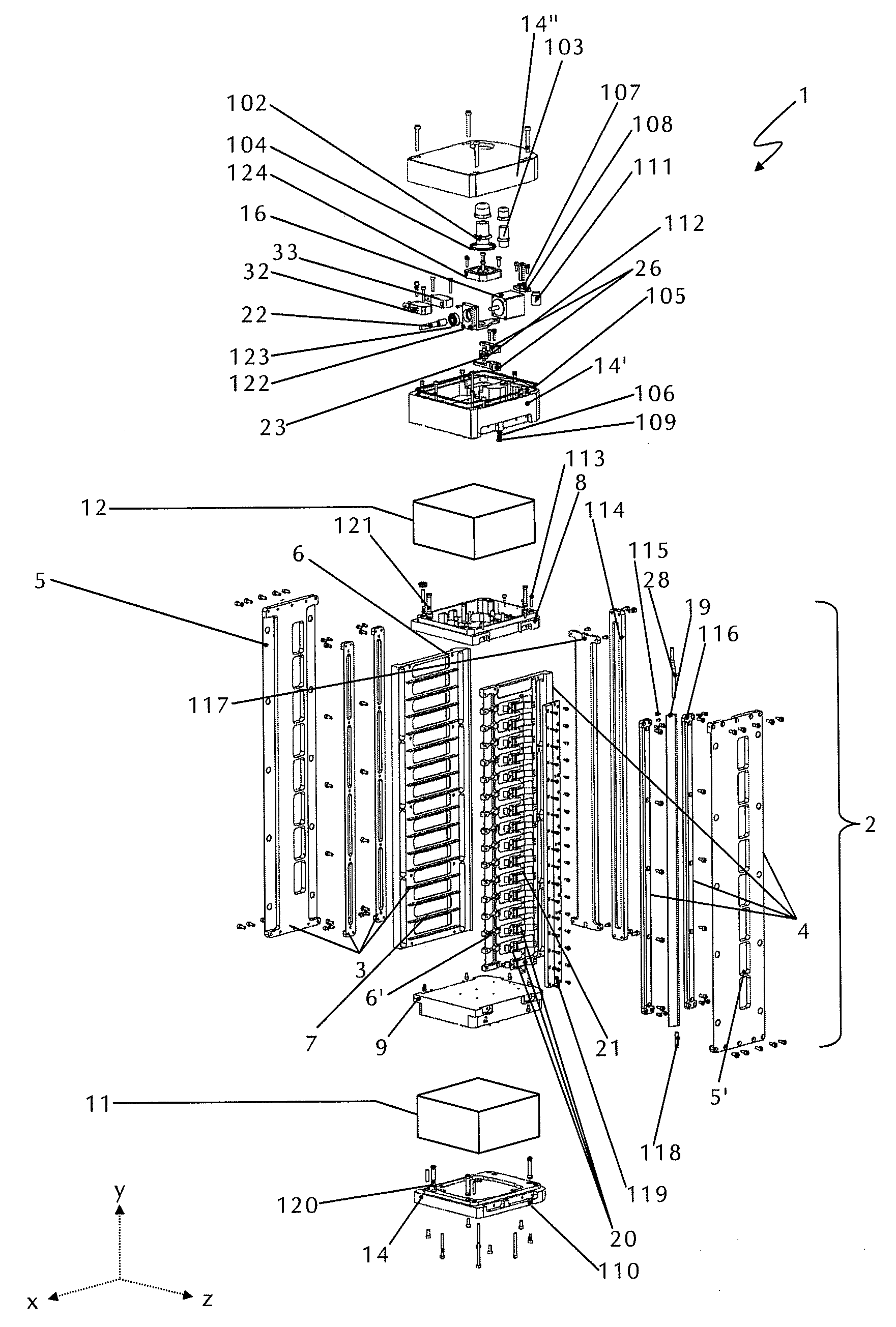
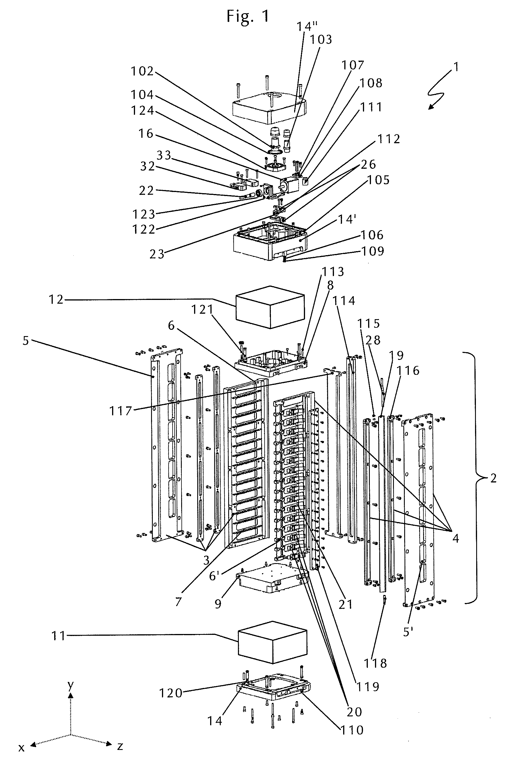
[0037]The object storage device 1 in FIG. 1 comprises a storage cassette 2 having two vertically running side walls 3 and 4, which each have, inter alia, a support 5 or 5′ and a ladder-like side wall plate 6 or 6′, respectively. Diametrically opposite rail-like guides 7 (solely indicated partially for the left side wall 3 in FIG. 1) are situated in pairs on the ladder-like side wall plates 6 and 6′ of the side walls 3 and 4, which are implemented for inserting and guiding objects (not shown) and in particular microtitration plates in the storage cassette 2. One guide pair (i.e., one rail-like side of the ladder 6 and one rail-like side of the ladder 6′ situated at the same height (not shown in FIG. 1)) thus establishes one object storage point of the object storage device 1. A spring plate 8 or 9 is situated above and below, respectively, the side walls 3 and 4,...


PUM

PropertyMeasurementUnit
areaaaaaaaaaaa
shaking movementaaaaaaaaaa
retention anglesaaaaaaaaaa

Abstract

The present invention relates to an object storage device having shaking function having a vertically situated storage cassette, which has multiple object storage points situated one on top of another, and having a drive unit functionally connected to the storage cassette via a first drive connection, comprising at least one drive element for performing a shaking movement of the storage cassette. The present invention also relates to a climatic cabinet having such an object storage device.

Description

CROSS-REFERENCE TO RELATED APPLICATIONS[0001]This application claims priority of German Patent Application DE 102007004072.7 filed Jan. 26, 2007, the contents of which is incorporated by reference in its entirety.BACKGROUND OF THE INVENTION[0002]The present invention relates to an object storage device having a shaking function having a vertically situated storage cassette, which has multiple object storage points situated one on top of another, and having a drive unit functionally connected to the storage cassette via a first drive connection, comprising a drive element for performing a shaking movement of the storage cassette. The present invention also relates to a climatic cabinet having an above-mentioned object storage device.[0003]An object storage device is understood in this context as a device in which objects may be received at multiple object storage points situated one on top of another in a tower. Multiple in the meaning of the present invention particularly means more...

Claims


Application Information

Patent Timeline
Patent Type & Authority Applications(United States)
IPC IPC(8): G11B23/02B01L99/00
CPCB01F11/0008B01F11/0014B01F11/0097G01N2035/00524C12M45/22G01N35/00029G01N2035/00089B01L9/523B01F31/201B01F31/22B01F31/70
Inventor KAUFMANN, KLAUSBETZ, STEFANLOSCHER, HELMUTHEEG, HUBERT
Owner THERMO ELECTRONICS LED GMBH
Why Eureka
Try Eureka